


6-6
Software Configuration Guide—Release 15.0(2)SG
OL-23818-01
Chapter 6 Configuring Interfaces
Using the Ethernet Management Port
Using the Ethernet Management Port
This section has this information:
• Understanding the Ethernet Management Port, page 6-6
• Supported Features on the Ethernet Management Port, page 6-9
• Configuring the Ethernet Management Port, page 6-10
Understanding the Ethernet Management Port
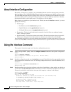
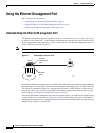
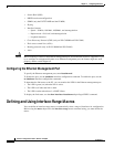
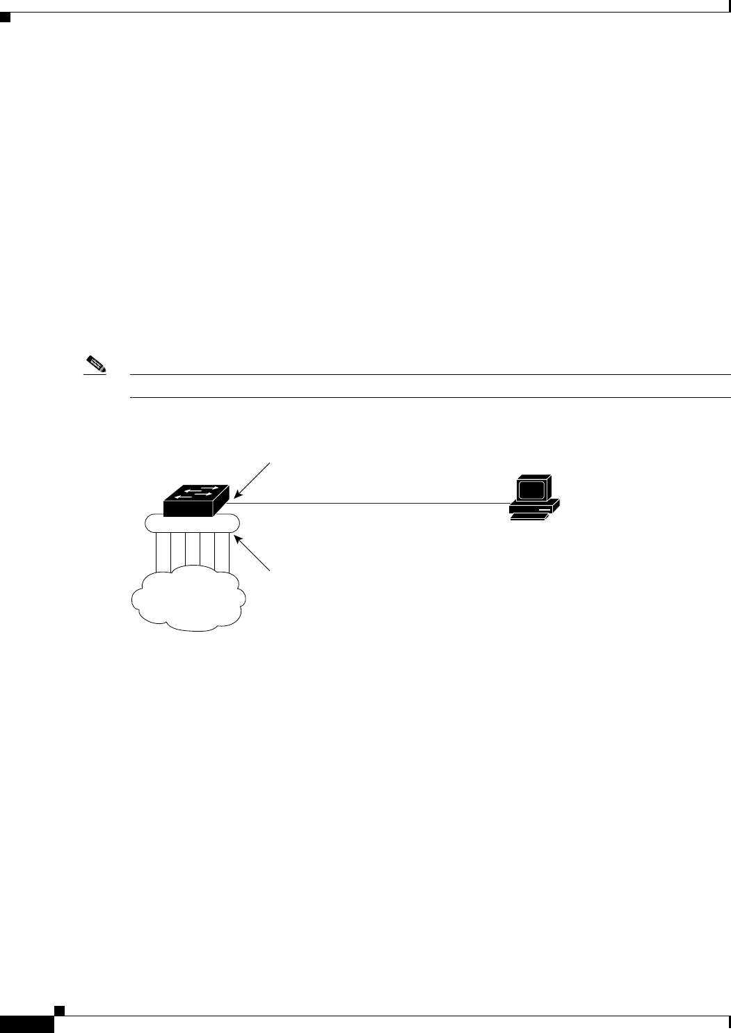
The Ethernet management port, also referred to as the Fa1 or fastethernet1 port, is a Layer 3 host port
to which you can connect a PC. Use the Ethernet management port instead of the switch console port for
network management. When managing a switch, connect the PC to the Ethernet management port on a
Catalyst 4500 series switch. (Figure 6-1).
Note When connecting a PC to the Ethernet management port, you must assign an IP address.
Figure 6-1 Connecting a Switch to a PC
By default, the Ethernet management port is enabled. The switch cannot route packets from the Ethernet
management port to a network port, and from the network port to the Ethernet port. To obtain these, the
Fa1 interface is automatically placed in a separate routing domain (or VRF domain), called mgmtVrf.
(You observe the ip Vrf forwarding mgmtVrf line in the running configuration when you boot up.) For
details, read the “Fa1 Interface and mgmtVrf” section on page 6-7.
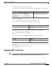
Even though the Ethernet management port does not support routing, you might need to enable routing
protocols on the port. As illustrated in Figure 6-2, you must enable routing protocols on the Ethernet
management port when the PC is multiple hops away from the switch and the packets must pass through
multiple Layer 3 devices to reach the PC.
157549
Switch
PC
Network
cloud
Ethernet
management
port
Network
ports