


8-9
Software Configuration Guide—Release 15.0(2)SG
OL-23818-01
Chapter 8 Configuring Supervisor Engine Redundancy Using RPR and SSO
Configuring Supervisor Engine Redundancy
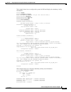
This example shows how to configure the system for SSO and display the redundancy facility
information:
Switch> enable
Switch# configure terminal
Enter configuration commands, one per line. End with CNTL/Z.
Switch(config)# redundancy
Switch(config-red)# mode sso
Switch(config-red)# end
Switch# show redundancy
Redundant System Information :
------------------------------
Available system uptime = 2 days, 2 hours, 39 minutes
Switchovers system experienced = 0
Standby failures = 0
Last switchover reason = none
Hardware Mode = Duplex
Configured Redundancy Mode = Stateful Switchover
Operating Redundancy Mode = Stateful Switchover
Maintenance Mode = Disabled
Communications = Up
Current Processor Information :
-------------------------------
Active Location = slot 1
Current Software state = ACTIVE
Uptime in current state = 2 days, 2 hours, 39 minutes
Image Version = Cisco Internetwork Operating System Software
IOS (tm) Catalyst 4000 L3 Switch Software (cat4000-I5S-M), Version 12.2(20)EWA(3
.92), CISCO INTERNAL USE ONLY ENHANCED PRODUCTION VERSION
Copyright (c) 1986-2004 by cisco Systems, Inc.
Compiled Wed 14-Jul-04 04:42 by esi
BOOT = bootflash:cat4000-i5s-mz.122_20_EWA_392,1
Configuration register = 0x2002
Peer Processor Information :
----------------------------
Standby Location = slot 2
Current Software state = STANDBY HOT
Uptime in current state = 2 days, 2 hours, 39 minutes
Image Version = Cisco Internetwork Operating System Software
IOS (tm) Catalyst 4000 L3 Switch Software (cat4000-I5S-M), Version 12.2(20)EWA(3
.92), CISCO INTERNAL USE ONLY ENHANCED PRODUCTION VERSION
Copyright (c) 1986-2004 by cisco Systems, Inc.
Compiled Wed 14-Jul-04 0
BOOT = bootflash:cat4000-i5s-mz.122_20_EWA_392,1
Configuration register = 0x2002
Switch#
This example shows how to display redundancy facility state information:
Switch# show redundancy states
my state = 13 -ACTIVE
peer state = 8 -STANDBY HOT
Mode = Duplex
Unit = Primary
Unit ID = 2
Redundancy Mode (Operational) = Stateful Switchover
Redundancy Mode (Configured) = Stateful Switchover
Redundancy State = Stateful Switchover
Maintenance Mode = Disabled