


36-3
Software Configuration Guide—Release 15.0(2)SG
OL-23818-01
Chapter 36 Configuring VRF-lite
Default VRF-lite Configuration
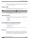
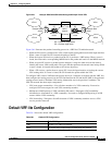
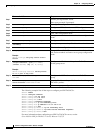
Figure 36-1 Catalyst 4500 Series Switches Acting as Multiple Virtual CEs
Figure 36-1 illustrates the packet-forwarding process in a VRF-lite CE-enabled network.
• When the CE receives a packet from a VPN, it looks up the routing table based on the input interface.
When a route is found, the CE forwards the packet to the PE.
• When the ingress PE receives a packet from the CE, it performs a VRF lookup. When a route is
found, the router adds a corresponding MPLS label to the packet and sends it to the MPLS network.
• When an egress PE receives a packet from the network, it strips the label and uses the label to
identify the correct VPN routing table. The egress PE then performs the normal route lookup. When
a route is found, it forwards the packet to the correct adjacency.
• When a CE receives a packet from an egress PE, it uses the input interface to look up the correct
VPN routing table. If a route is found, the CE forwards the packet within the VPN.
To configure VRF, create a VRF table and specify the Layer 3 interface associated with the VRF. You
then configure the routing protocols in the VPN and between the CE and the PE. BGP is the preferred
routing protocol used to distribute VPN routing information across the providers’ backbone. The
VRF-lite network has three major components:
• VPN route target communities—Lists all other members of a VPN community. You need to
configure VPN route targets for each VPN community member.
• Multiprotocol BGP peering of VPN community PE routers—Propagates VRF reachability
information to all members of a VPN community. You need to configure BGP peering in all PE
routers within a VPN community.
• VPN forwarding—Transports all traffic between all VPN community members across a VPN
service-provider network.
Default VRF-lite Configuration
Table 36-1 shows the default VRF configuration.
VPN 1
VPN 2
VPN 1
VPN 2
CE
MPLS-VRF
router
MPLS-VRF
router
Catalyst 4500
switch
Catalyst 4500
switch
PE PE
MPLS
network
CE
CE = Customer edge device
PE = Provider edge router
99721
Si Si
Table 36-1 Default VRF Configuration
Feature Default Setting
VRF Disabled. No VRFs are defined.
Maps No import maps, export maps, or route maps are defined.