


4-34
Cisco uBR7225VXR Universal Broadband Router Hardware Installation Guide
OL-17309-02
Chapter 4 Connecting the Cisco uBR7225VXR Router to the Cable Headend
Measuring the Upstream RF Signal
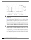
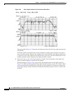
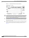
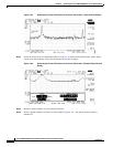
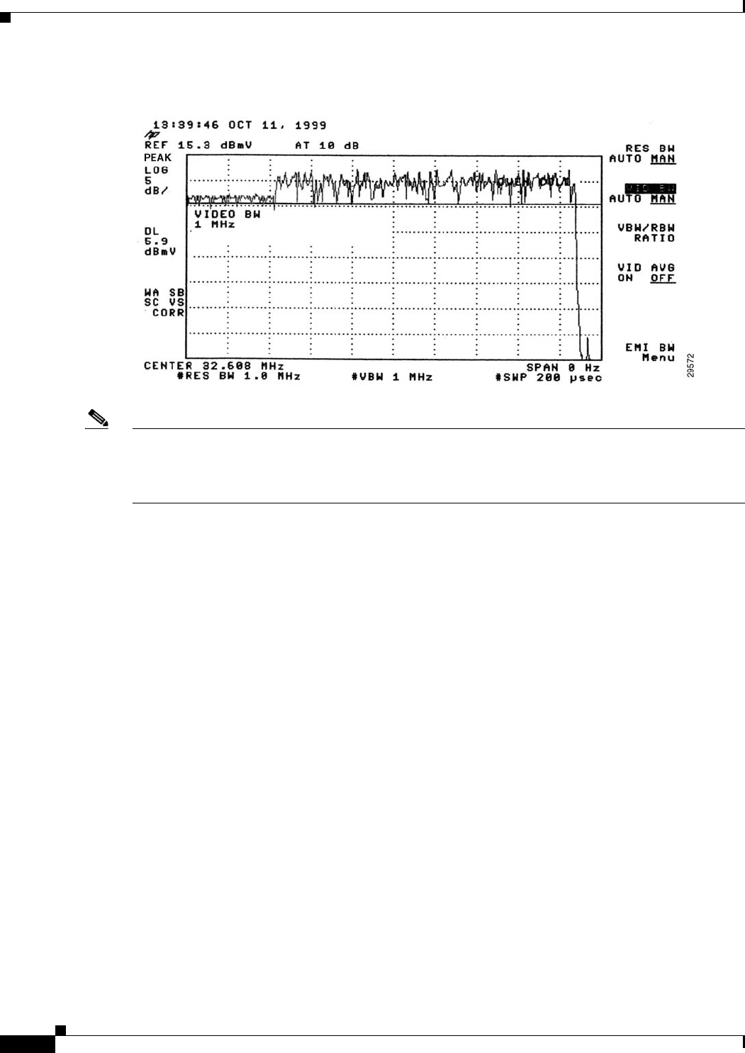
Figure 4-39 Preamble Amplitude Before Center Frequency Adjustment
Note The slight amplitude variations shown in these figures are normal signal level variations between bursts
in the upstream channel. Expect modems to vary upstream transmit power by nearly 1 dB between
bursts. This is well within the requirements for DOCSIS compliance. The default variation between
modems is up to 1.5 dB for most DOCSIS CMTS equipment.
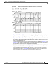
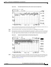
Step 4 Using the examples in Table 4-2 on page 4-28 as a basis for the formula, calculate the correct center
frequency offset necessary to measure the preamble peak power when viewed in a narrow bandwidth.
In the example, the channel width is 1.6 MHz, which has a symbol rate of 1280 ksym/sec; therefore, the
appropriate offset value is 640 kHz.
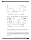
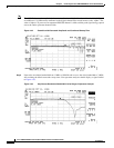
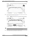
Step 5 Change the center frequency on the spectrum analyzer by this offset value (33.248 MHz in the example)
and check to see that the preamble has regained its lost amplitude by comparing it to the amplitude of
the rest of the signal. If so, the spectrum analyzer should display a signal similar to the one in
Figure 4-40.