


4-13
Cisco uBR7225VXR Universal Broadband Router Hardware Installation Guide
OL-17309-02
Chapter 4 Connecting the Cisco uBR7225VXR Router to the Cable Headend
Measuring the Downstream RF Signal
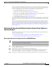
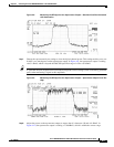
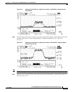
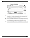
Figure 4-14 Measuring the IF Signal on a Spectrum Analyzer in CATV Mode—Digital Channel
Power Screen
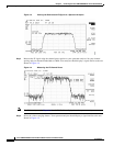
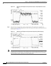
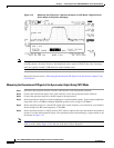
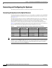
Step 6
Using the spectrum analyzer’s reference level control, adjust the amplitude of the displayed signal until
the shape of the signal is clearly distinguishable as a digitally modulated carrier, as shown in
Figure 4-15.
Figure 4-15 Measuring the IF Signal on a Spectrum Analyzer in CATV Mode—Adjusted Digital
Channel Power Screen
Note The IF channel power in Figure 4-15 is +33 dBmV, as displayed on the spectrum analyzer.
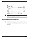
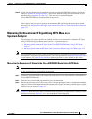
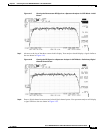
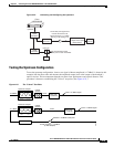
Step 7 Select the video averaging feature. Your spectrum analyzer should display a signal similar to the one
shown in Figure 4-16.