


4-4
Cisco uBR7225VXR Universal Broadband Router Hardware Installation Guide
OL-17309-02
Chapter 4 Connecting the Cisco uBR7225VXR Router to the Cable Headend
Connecting and Configuring the Downstream
• Noise funneling—The upstream data path to the headend is susceptible to picking up noise and
interference from anywhere in the network, and all upstream noise ultimately ends up at the
headend. This effect is known as noise funneling because of the cumulative nature of the noise from
one or more locations in the network that becomes concentrated at the headend. As a network
serviced by a single upstream receiver increases in size, the probability of noise funneling also
increases.
• Variable transmit levels—Signal loss over coaxial cable is affected by temperature. This can cause
variations of 6 to 10 dB per year.
• Clipping—The lasers in fiber-optic transmitters can stop transmitting light (clipping) when input
levels are excessive. Excessive input levels may cause bit errors and reduced data throughput in both
the upstream and downstream transmissions. If a laser is overdriven as briefly as a fraction of a
second, clipping can occur.
Connecting and Configuring the Downstream
After you install the Cisco uBR7225VXR universal broadband router in your headend site, you must
connect the Cisco uBR7225VXR router to the HFC network and configure the network. The following
sections describe how to connect to and configure the downstream.
Installing and Configuring the Upconverter
The Cisco uBR-MC16U/E-16U and Cisco uBR-MC28U/E-28U cable interface line cards have an
onboard integrated upconverter that generates an RF signal suitable for connection to a combiner and
transmission on the coaxial cable network, without the need for any external upconverters.
Note For more information, refer to the Cisco uBR7200 Series Cable Interface Line Card Hardware
Installation Guide at the following URL:
http://www.cisco.com/en/US/docs/interfaces_modules/cable/line_cards/installation/guide/mcxxfru.htm
l
Measuring the Downstream RF Signal
The configuration of the downstream digitally modulated carrier at the headend is critical to the
performance of the Cisco uBR7225VXR universal broadband router and cable modems. The following
guidelines are provided to assist you in configuring the RF signal to the necessary specifications. There
are two options you can use to measure the RF signal with a spectrum analyzer. These options are
described in the following sections:
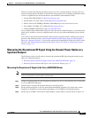
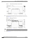
• Measuring the Downstream RF Signal Using the Channel Power Option on a Spectrum Analyzer,
page 4-5
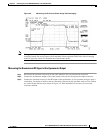
• Measuring the Downstream RF Signal Using CATV Mode on a Spectrum Analyzer, page 4-11
(equipped with digital channel power mode)