


4-18
Cisco uBR7225VXR Universal Broadband Router Hardware Installation Guide
OL-17309-02
Chapter 4 Connecting the Cisco uBR7225VXR Router to the Cable Headend
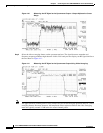
Connecting and Configuring the Upstream
Connecting and Configuring the Upstream
The following sections describe how to connect and configure the upstream for digital data.
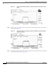
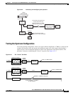
Connecting the Upstream to the Optical Receiver
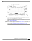
To connect the upstream to the optical receiver, use a 2-way splitter as a combiner to leave the DOCSIS
cable modem connected at the headend, and connect the upstream headend cable to the optical receiver.
(See Figure 4-22.)
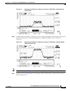
The default upstream input level to the Cisco uBR7225VXR cable interface line card is 0 dBmV. You
may adjust the upstream input level to other values using the Cisco IOS software running on your router.
The Cisco uBR7225VXR router uses automatic power control when transmitting to remote
cable modems. Accurately setting the power level helps to ensure reliable cable modem operation.
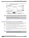
Table 4-1 provides upstream input power ranges for the various cable interface line cards available for
the Cisco uBR7225VXR router, depending on the channel bandwidth you are using.
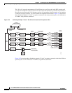
Note If you have a Cisco uBRMC16x cable interface line card (six upstream ports and one downstream port)
installed in your Cisco uBR7225VXR router, the 2-way splitter described above would be replaced by
six 2-way splitters (one splitter per upstream port). This would enable you to connect to all of the
available upstream ports on the Cisco uBRMC16x.
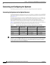
Table 4-1 Upstream Input Power Ranges According to Cable Interface Line Card Type
Channel Bandwidth Cisco MC11 FPGA Cisco MC16E and MC16S DOCSIS Specification
200 KHz N/A –10 to +25 dBmV –16 to +14 dBmV
400 KHz N/A –10 to +25 dBmV –13 to +17 dBmV
800 KHz N/A –10 to +25 dBmV –10 to +20 dBmV
1.6 MHz –10 to +10 dBmV –10 to +25 dBmV –7 to +23 dBmV
3.2 MHz N/A –10 to +25 dBmV –4 to +26 dBmV