


4-17
Cisco uBR7225VXR Universal Broadband Router Hardware Installation Guide
OL-17309-02
Chapter 4 Connecting the Cisco uBR7225VXR Router to the Cable Headend
Measuring the Downstream RF Signal
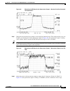
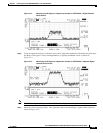
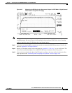
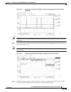
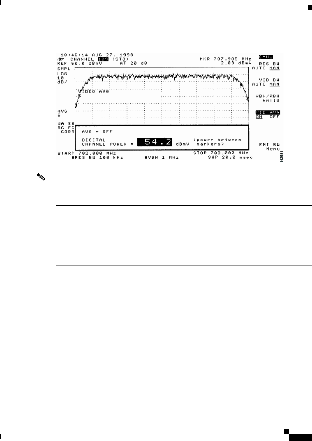
Figure 4-21 Measuring the RF Signal at the Upconverter Output in CATV Mode—Digital Channel
Power Screen Using Video Averaging
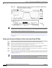
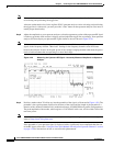
Note The approximate in-channel peak-to-valley flatness can be verified using the spectrum analyzer’s video
averaging feature. Be aware, however, that amplitude values registered while in the video averaging
mode are typically around 2.5 dB below the actual channel power.
Step 11 Verify that your headend RF measurements meet the recommended DOCSIS parameters listed in the
tables in Appendix B, “RF Specifications.”
Step 12 Record your headend settings and measurements in Appendix G, “Site Log.” as you verify them. This
will assist in troubleshooting the Cisco uBR7225VXR router installation later in the process.
Step 13 After you have analyzed and adjusted the RF signal according to the steps outlined on the preceding
pages, proceed to the “Connecting and Configuring the Upstream” section on page 4-18.