


3-13
Cisco uBR7225VXR Universal Broadband Router Hardware Installation Guide
OL-17309-02
Chapter 3 Installing the Cisco uBR7225VXR Router
Cabling
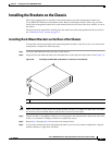
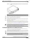
Step 3 Add the five rubber feet supplied with the accessory kit to the base of the chassis. Five indented circles
are provided on the base of the chassis to indicate the location to which the rubber feet can be added.
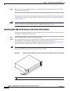
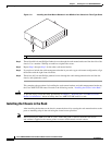
Step 4 Place the Cisco uBR7225VXR router on the tabletop or workbench.
Step 5 Ensure that there is the appropriate amount of space around the router.
If you want to install a cable-management bracket on the Cisco uBR7225VXR router, proceed to the
following section, “Installing the Cable-Management Bracket on a Cisco uBR7225VXR Router in a
Workbench or Tabletop Environment.” Otherwise, proceed to the “Cabling” section on page 3-13.
Installing the Cable-Management Bracket on a Cisco uBR7225VXR Router in a
Workbench or Tabletop Environment
To install the cable-management bracket on a Cisco uBR7225VXR universal broadband router installed
on a workbench or tabletop, complete the following steps:
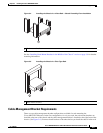
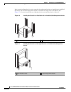
Step 1 Locate the threaded holes in the right front side of the chassis.
Step 2 Align the cable-management bracket with the two threaded holes on the front or rear side of the
Cisco uBR7225VXR chassis. (See Figure 3-7 on page 3-6.)
Step 3 Thread two M3 x 6-mm Phillips panhead screws through the bracket and into the chassis. Use a number
2 Phillips screwdriver to tighten the screws.
This completes the steps for installing the cable-management bracket on the Cisco uBR7225VXR router.
Proceed to, “Cabling” section on page 3-13 to continue the installation.
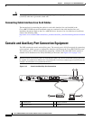
Cabling
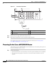
This section provides information on connecting cable interface cards, auxiliary and console ports to
your Cisco uBR7225VXR universal broadband router.
Warning
This product is not intended to be directly connected to the Cable Distribution System. Additional
regulatory compliance and legal requirements may apply for direct connection to the Cable
Distribution System. This product may connect to the Cable Distribution System ONLY through a device
that is approved for direct connection.
Statement 1078
Warning
The intra-building port(s) of the equipment or subassembly is suitable for connection to intra-building
or unexposed wiring or cabling only. The intra-building port(s) of the equipment or subassembly
MUST NOT metallically connect to interfaces that connect to the OSP or its wiring. These interfaces
are designed for use as intra-building interfaces only (Type 2 or Type 4 ports as described in
GR-1089-CORE, Issue 4) and require isolation from the exposed OSP cabling. The addition of Primary
Protectors is not sufficient protection in order to connect these interfaces metallically to OSP wiring.
Statement 7005