


1-4
Cisco uBR7225VXR Universal Broadband Router Hardware Installation Guide
OL-17309-02
Chapter 1 Cisco uBR7225VXR Overview
Cisco uBR7225VXR Network Interface Overview
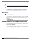
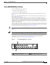
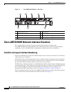
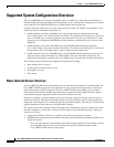
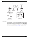
Figure 1-2 Cisco uBR7225VXR Router—Rear View
Cisco uBR7225VXR Network Interface Overview
This section provides a functional overview of the network interfaces available on the
Cisco uBR7225VXR universal broadband router, cable interface line card slot and logical interface
numbering, as well as the MAC address assignments for cable interface line card interfaces.
Card Slot and Logical Interface Numbering
In the Cisco uBR7200 series universal broadband routers, the slot number is the chassis slot in which a
cable interface card is installed.
Cable interface line card slots maintain the same slot number regardless of whether other cable interface
line cards are installed or removed. However, when you move a cable interface line card to a different
slot, the logical interface number changes to reflect the new slot number.
The MAC-layer or hardware address is a standardized data-link layer address that is required for certain
network interface types. These addresses are specific and unique to each port. The Cisco uBR7225VXR
uses a specific method to assign and control the MAC-layer addresses of its port adapters. For a
description of the MAC-layer address, refer to the “MAC-Layer Address” section on page 1-5.
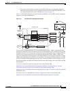
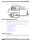
The two cable interface line cards in the Cisco uBR7225VXR router provide the connection between the
router’s two PCI buses (mb1 and mb2) and external networks. See Figure 1-3.
1
Gigabit Ethernet 0/1
5
Console port
2
Gigabit Ethernet 0/2
6
Auxiliary port
3
Gigabit Ethernet 0/3
7
AC-input power supply 2
4
CompactFlash Disk slot
8
AC-input power supply 1
270490
uBR7225-VXR
uBR7225-VXR
1 2 3 4 5
8 7 6