


1-12
Cisco uBR7225VXR Universal Broadband Router Hardware Installation Guide
OL-17309-02
Chapter 1 Cisco uBR7225VXR Overview
Hardware Component Descriptions
–
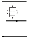
Cisco uBR7200-NPE-G2—SDRAM: 1 GB (default) and 2 GB. There are two DRAM memory
slots, so 1 GB of memory consists of two 512-MB memory SODIMMs, and 2 GB consists of
two 1 GB memory SODIMMs. It is necessary to have the same size SODIMM in each memory
bank on an NPE-G2. The type of DRAM memory being used on the NPE-G2 is double data-rate
(DDR) memory. DDR memory provides high-performance memory access rates.
• Cache memory:
–
Cisco uBR7200-NPE-G1—16-MB packet memory on 256-MB SDRAM, and 32-MB packet
memory on 512-MB and 1-GB SDRAM.
–
Cisco uBR7200-NPE-G2—32-MB packet memory on 512-MB and 1-GB SDRAM.
• Two environmental sensors for monitoring the cooling air as it leaves the chassis.
• Boot ROM for storing sufficient code for booting the Cisco IOS software.
For memory replacement instructions, refer to the Memory Replacement Instructions for the Network
Processing Engine or Network Services Engine and Input/Output Controller document at the following
URL:
http://www.cisco.com/en/US/docs/routers/7200/install_and_upgrade/npe-nse_memory_install/memory
.html
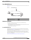
Cisco Cable Interface Line Cards
Cisco cable interface line cards (also known as line cards), with internal IF-to-RF upconverters, serve as
the RF interface between the cable headend and both DOCSIS-based cable modems and
EuroDOCSIS-based cable modems and set-top boxes (STBs). Cisco cable interface line cards separate
downstream output and upstream input cable interfaces on the Cisco uBR7225VXR router to enable
downstream and upstream signal combining and splitting arrangements.
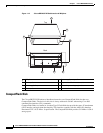
Cisco cable interface line cards can be used in both 6-MHz NTSC standard and 8-MHz PAL/SECAM
channel environments.
The cable interface line cards connect directly to the universal broadband router’s midplane. Cable
interface line cards installed in the Cisco uBR7225VXR router support OIR.
Caution To ensure the proper flow of cooling air across internal components, make sure that blank cable interface
line card is installed in an unoccupied chassis slot. Also make sure that power supply filler plates are
installed in unoccupied power supply bays.
For more information regarding specific cable interface line cards, refer to the Cisco uBR7200 Series
Cable Interface Line Card Hardware Installation Guide. To view the document online, go to the
following URL:
http://www.cisco.com/en/US/docs/interfaces_modules/cable/line_cards/installation/guide/mcxxfru.htm
l