


4-7
Cisco uBR7225VXR Universal Broadband Router Hardware Installation Guide
OL-17309-02
Chapter 4 Connecting the Cisco uBR7225VXR Router to the Cable Headend
Measuring the Downstream RF Signal
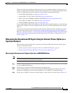
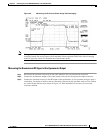
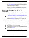
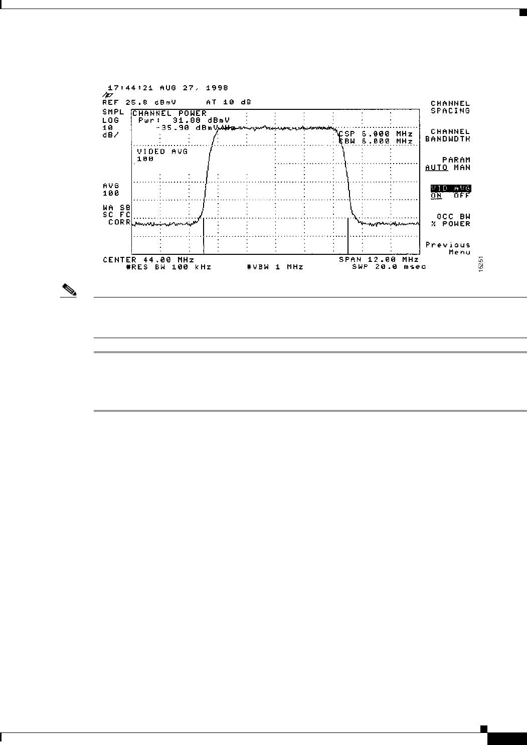
Figure 4-5 Measuring the IF Channel Power Using Video Averaging
Note The approximate in-channel peak-to-valley flatness may be verified using the spectrum analyzer’s video
averaging feature. Be aware, however, that amplitude values registered while in the video averaging
mode are typically around 2.5 dB below the actual channel power.
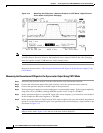
Measuring the Downstream RF Signal at the Upconverter Output
Step 1 Disconnect the spectrum analyzer from the cable interface line card downstream connector.
Step 2 Connect the downstream output of the cable interface line card to the upconvertor input connector.
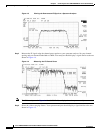
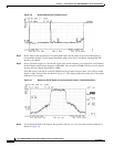
Step 3 Connect the spectrum analyzer to the RF output of the upconverter. If your spectrum analyzer input is
overloaded, you might see artifacts that are internally generated by the spectrum analyzer. The artifacts
are circled on the analyzer trace shown in Figure 4-6. Add attenuation as necessary to correct the
overload condition.