


4-9
Cisco uBR7225VXR Universal Broadband Router Hardware Installation Guide
OL-17309-02
Chapter 4 Connecting the Cisco uBR7225VXR Router to the Cable Headend
Measuring the Downstream RF Signal
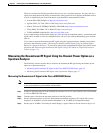
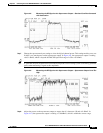
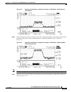
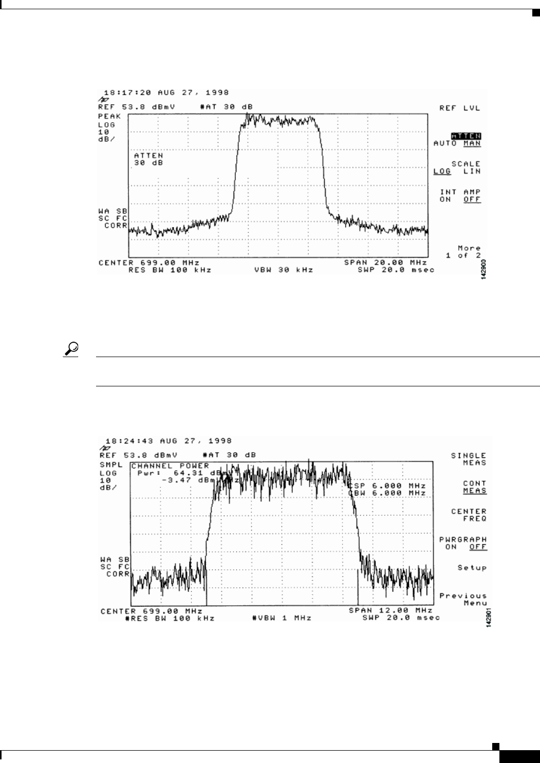
Figure 4-8 Measuring the RF Signal at the Upconverter Output—Overload Condition Corrected
with Attenuation
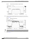
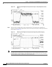
Step 7
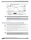
Change the spectrum analyzer settings to view the digital channel power. This setting enables you to see
if there is too much power on the upconverter output. In Figure 4-9, the upconverter output is reading
+64.31 dBmV, which is beyond the DOCSIS-specified range of +50 to +61 dBmV.
Tip A spectrum analyzer might become overloaded and produce false readings (such as internally generated
spurs) when measuring a signal at this amplitude.
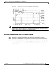
Figure 4-9 Measuring the RF Signal at the Upconverter Output—Upconverter Output Level Too
High
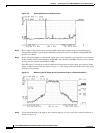
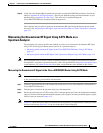
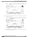
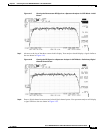
Step 8
Adjust the power on the upconverter output to ensure that it is between +50 and +61 dBmV. In
Figure 4-10, the upconverter output is reading +57.06 dBmV, which is within the correct range.