


1-17
Cisco uBR7225VXR Universal Broadband Router Hardware Installation Guide
OL-17309-02
Chapter 1 Cisco uBR7225VXR Overview
Hardware Component Descriptions
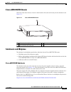
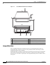
Cisco uBR7225VXR Chassis
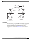
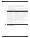
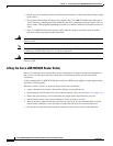
The front of the chassis has two slots for cable interface line cards and one bay for the subchassis. See
Figure 1-11.
Figure 1-11 Cisco uBR7225VXR Chassis
Subchassis and Midplane
The subchassis and midplane provide these functions for the Cisco uBR7225VXR router:
• Distributes power from the power supply.
• Bridges the peripheral component interconnect (PCI) buses from the cable interface line cards to the
Cisco uBR7200-NPE-G1 or the Cisco uBR7200-NPE-G2.
• Arbitrates traffic across the PCI buses.
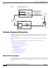
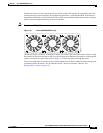
Cisco uBR7225VXR Subchassis
The subchassis (the rear of the router) has two bays for power supplies and one slot for a network
processing engine. (See Figure 1-12.) The cable interface card side of the Cisco uBR7225VXR router
midplane has two connectors for cable interface line cards.
The power supply side of the midplane has two connectors for power supplies and one connector for a
network processing engine. The midplane supplies DC power to the router’s internal components.
Refer to the Cisco uBR7200 Series Universal Broadband Router Subchassis and Midplane Replacement
Instructions at the following URL:
http://www.cisco.com/en/US/docs/cable/cmts/ubr7200/installation/5193sbm.html
270494
u
BR
7
2
2
5
-V
X
R
1
2
3
1
Subchassis and midplane bay (at rear)
3
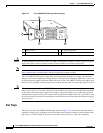
Fan tray
2
Cable interface line card slots