


1-14
Cisco uBR7225VXR Universal Broadband Router Hardware Installation Guide
OL-17309-02
Chapter 1 Cisco uBR7225VXR Overview
Hardware Component Descriptions
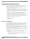
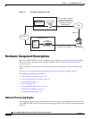
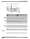
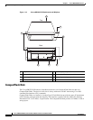
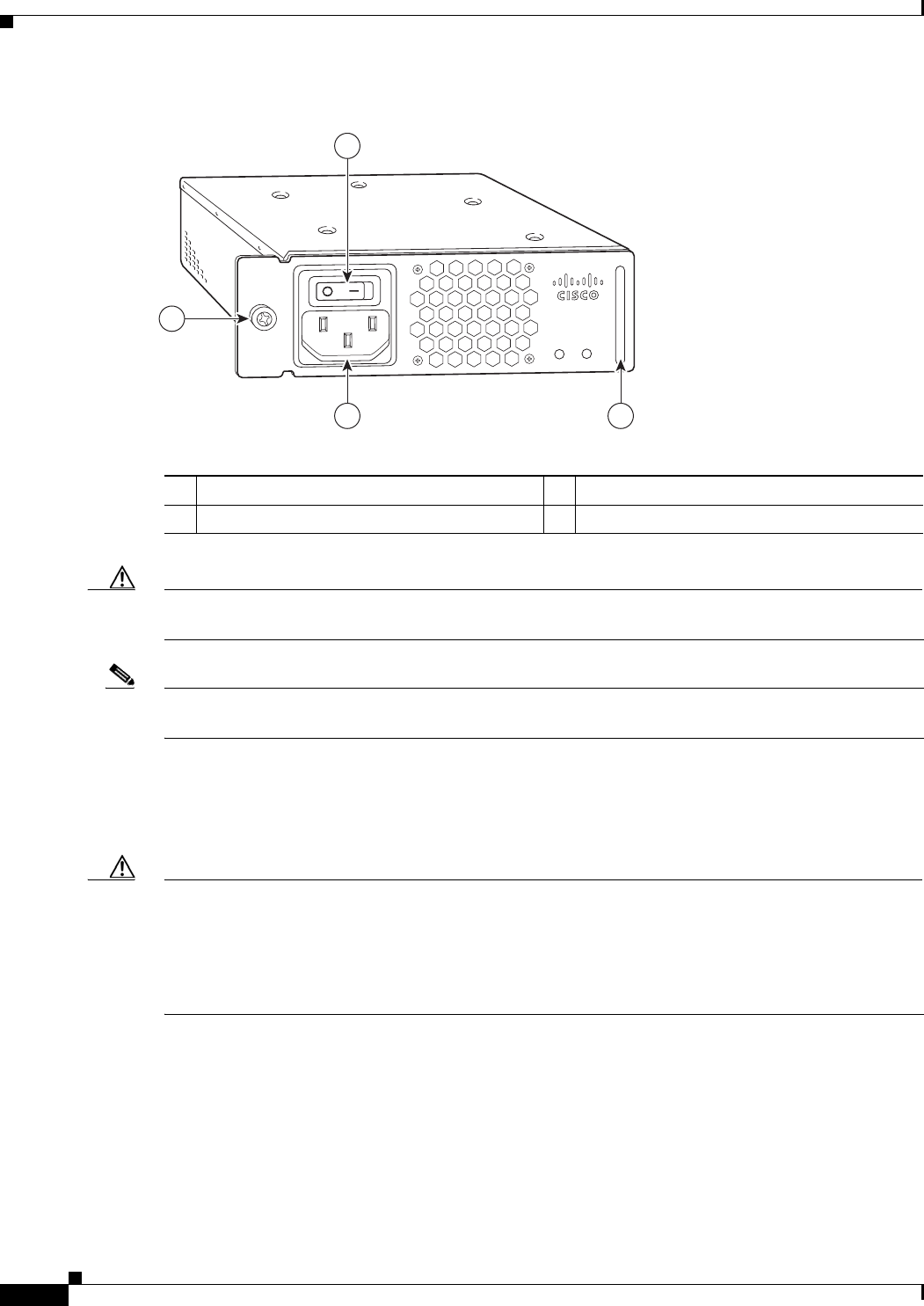
Figure 1-8 Cisco uBR7225VXR AC-Input Power Supply
Caution To ensure adequate airflow across the Cisco uBR7225VXR power supplies, a power supply or a power
supply filler plate (with its attached air dam) must be installed in each power supply bay.
Note See Appendix A, “Cisco uBR7225VXR Router Specifications,” for AC-input power supply system
power specifications, including input voltage and operating frequency ranges.
The Cisco uBR7225VXR power supply shuts itself down when the input AC voltage, the output DC
voltage, or the internal temperature of the chassis exceeds allowable tolerances. When this occurs, one
or both of the power supply front panel LEDs will turn red. The Cisco uBR7225VXR power supply must
then be reset by manually switching the power switch off and then back on to allow the router to recover.
Caution When the input power to Cisco uBR7225VXR power supply is disconnected or lost, the power supply
enters a reset cycle for 10 seconds. Wait at least 10 seconds or move the power switch from one position
to the other to restart the power supply. For example, if the power supply was on when the power was
disconnected or lost, move the power switch to the off position and then back to the on position. If you
do not wait the full 10 seconds or move the power switch from one position to the other, the power supply
does not restart.
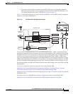
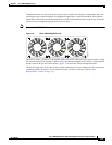
Fan Trays
The fan tray for the Cisco uBR7225VXR router, shown in Figure 1-9, consisting of three fans that are
attached to a metal tray, is located on the left side of the chassis (when viewing the router from the front)
and receives 12 VDC through a DC power harness that connects directly to the router midplane.
270698
PWR-UBR7225VXR-AC
100
-240 VA
C
4-2 A
50-60 Hz
Input
OK
Output
OK
1
23
4
1
Power switch
3
AC-input receptable
2
Handle
4
Captive installation screw