


4-25
Cisco uBR7225VXR Universal Broadband Router Hardware Installation Guide
OL-17309-02
Chapter 4 Connecting the Cisco uBR7225VXR Router to the Cable Headend
Measuring the Upstream RF Signal
Step 10 Verify that your headend RF measurements meet the recommended DOCSIS parameters listed in the
tables in Appendix B, “RF Specifications.”
Step 11 Record your headend settings in Appendix G, “Site Log.” This will assist in troubleshooting the
Cisco uBR7225VXR universal broadband router installation later in the process.
Note Be sure not to narrow the focus of your analysis any further than approximately 3-MHz channel width.
Doing so can yield incorrect readings. For example, if you were to view an upstream RF signal with a
resolution bandwidth of only 300 kHz and a video channel bandwidth of only 100 kHz, your
measurements would register lower than the actual transmission levels.
Analyzing the Upstream RF Signal
When you have set up your spectrum analyzer to accurately read the upstream RF signal, you can verify
that a remote cable modem is operating as it should by pinging the modem via a console terminal.
Step 1 Log in to your Cisco uBR7225VXR universal broadband router with a console terminal.
Step 2 Adjust the sweep time on your spectrum analyzer to 20 microseconds.
Step 3 Ping the remote cable interface card using first a 64-byte, then a 1500-byte ping packet request, and take
note of the upstream RF signal in each case. Several hundred or thousand ping packets might be required
for a usable pattern to emerge.
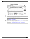
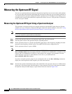
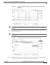
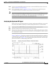
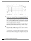
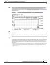
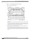
Figure 4-29 and Figure 4-30 provide two examples of an ideal upstream RF signal based on a simple 64-
or 1500-byte ping of a single remote cable interface. The more slender of the data spikes in the RF signal
(the first and third spikes in Figure 4-29) are bandwidth request packet transmissions, while the larger
spikes are the actual 64- or 1500-byte ping packet returns.
Figure 4-29 Analyzing the Upstream RF Signal—64-Byte Data Packets