


6-3
Cisco uBR7225VXR Universal Broadband Router Hardware Installation Guide
OL-17309-02
Chapter 6 Troubleshooting
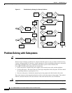
Problem Solving with Subsystems
• Cable headend subsystem—External to the Cisco uBR7225VXR router, this subsystem can prevent
operation of the universal broadband router if the headend is not properly set up for the introduction
of digital data into the hybrid fiber-coaxial (HFC) network.
The following section helps you isolate a problem to one of the subsystems and directs you to the
appropriate troubleshooting section.
Identifying Startup Problems
When you start up the Cisco uBR7225VXR router for the first time, observe the startup sequence
described in the “Powering On the Cisco uBR7225VXR Router” section on page 3-18. This section
contains a detailed description of the normal startup sequence.
Although an overtemperature condition is unlikely at initial startup, the environmental monitoring
functions are included in this chapter because they also monitor internal voltages.
Startup problems are commonly caused by source power problems or a board (network processing
engine or cable interface line card) that is not properly connected to the midplane. Always check that
your boards are properly installed in the chassis.
With the exception of the fan tray and network processing engine, LEDs indicate all system states in the
startup sequence. By checking the state of the LEDs, you can determine when and where the system
failed in the startup sequence.
Note On rare occasions, an LED may be faulty.
Use the following descriptions to isolate the problem to a subsystem, then proceed to the appropriate
sections to try to resolve the problem. When you start up the system, by turning on the power supply
switch, the following should occur:
1. You should immediately hear the fans operating. If not, proceed to the “Cooling Subsystem” section
on page 6-4. If you determine that the power supply is functioning normally and that a fan is faulty,
contact a customer service representative. If a fan does not function properly at initial startup, there
are no installation adjustments that you should make.
2. The power supply’s green Input OK LED (at the rear of the chassis) should go on immediately when
you place the power supply switch in the ON (|) position, and should remain on during normal
system operation. If the green Input OK LED does not go on, proceed to the “Power Subsystem”
section on page 6-4.
3. The enabled LED on each cable interface line card comes on when the network processing engine
completes its initialization of the card for operation. The enabled LED indicates that the line card is
receiving power and has been recognized by the network processing engine; it does not indicate the
state of the individual interfaces on the card. If an enabled LED fails to come on, refer to the
“Troubleshooting Cable Interface Line Cards” section on page 6-6.
4. When all LEDs come on to indicate that the system has booted successfully, the initial system
banner should appear on the console screen. If it is not displayed, refer to the “Console and
Auxiliary Port Connection Equipment” section on page 3-14 to verify that the terminal is set
correctly and that it is properly connected to the console port on the NPE.