


B-3
Cisco uBR7225VXR Universal Broadband Router Hardware Installation Guide
OL-17309-02
Appendix B RF Specifications
DOCSIS 1.0 Transmission Characteristics
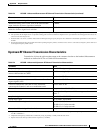
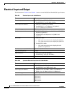
Upstream RF Channel Transmission Characteristics
Transmission is from the cable modem output at the customer location to the headend. Measurement
methods are defined in NCTA or CableLabs2 documentation.
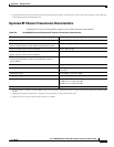
Seasonal and diurnal signal level variation 8 dB
Maximum analog video carrier level at the cable modem
input, inclusive of above signal level variation
17 dBmV
Lowest analog video carrier level at the cable modem input,
inclusive of above signal level variation
–5 dBmV
1. For measurements above the normal operating frequency band (except hum), impairments are referenced to the highest-frequency NTSC carrier level.
2. This presumes that the digital carrier is operated at analog peak carrier level. When the digital carrier is operated below the analog peak carrier level, the
carrier-to-noise ratio may be less.
3. Decibels relative to carrier, a common measurement in RF engineering to specify the power of a sideband in a modulated signal relative to the carrier in
decibels.
4. For hum measurements above the normal downstream operating frequency band, a continuous-wave carrier is sent at the test frequency at the same level
as the highest-frequency NTSC carrier.
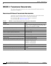
Table B-3 DOCSIS 1.0 Assumed Downstream RF Channel Transmission Characteristics (continued)
Parameter Value
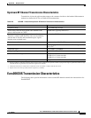
Table B-4 DOCSIS 1.0 Assumed Upstream RF Channel Transmission Characteristics
Parameter Value
Frequency range 5 to 42 MHz edge to edge
Transit delay from the most distant cable modem to the
nearest cable modem or CMTS
≤ 0.800 msec (typically much less)
Carrier-to-noise ratio Not less than 25 dB
Carrier-to-ingress power (the sum of discrete and broadband
ingress signals) ratio
Not less than 25 dB
1
1. Ingress avoidance or tolerance techniques may be used to ensure operation in the presence of time varying discrete ingress signals that could be as high
as 0 dBc. (CableLabs1)
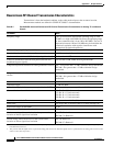
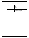
Carrier-to-interference (the sum of noise, distortion,
common-path distortion, and cross-modulation) ratio
Not less than 25 dB
Carrier hum modulation Not greater than –23 dBc (7%)
Burst noise Not longer than 10 μsec at a 1-kHz average rate for most
cases
2,
3
2. Amplitude and frequency characteristics sufficiently strong to partially or wholly mask the data carrier.
3. Impulse noise levels more prevalent at lower frequencies (<15 MHz).
Amplitude ripple 5 to 42 MHz: 0.5 dB/MHz
Group delay ripple 5 to 42 MHz: 200 ns/MHz
Micro-reflections—single echo –10 dBc @ ≤ 0.5 microseconds
–20 dBc @ ≤ 1.0 microseconds
–30 dBc @ > 1.0 microseconds
Seasonal and diurnal signal level variation Not greater than 8 dB min to max