


4-40
Cisco uBR7225VXR Universal Broadband Router Hardware Installation Guide
OL-17309-02
Chapter 4 Connecting the Cisco uBR7225VXR Router to the Cable Headend
Configuring the Digital Signal
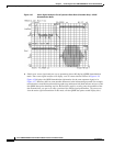
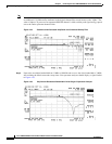
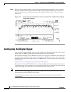
Step 8 Select the video averaging feature to verify flatness through the headend combiner. After 10 averages,
the power rating decreases by approximately 2.5 dB from actual digital channel power. While video
averaging is in progress, your spectrum analyzer should display a signal similar to the one shown in
Figure 4-49.
Figure 4-49 Downstream Forward Test Point on the Laser Transmitter—Digital Channel Display
Using Video Averaging
Configuring the Digital Signal
After you have configured the RF signal, you must configure the digital data signal that will be carried
between the Cisco uBR7225VXR universal broadband router and cable modems.
We recommend installing a Cisco uBR900 series cable access router at the headend to verify the digital
data configuration. For instructions on how to install a Cisco uBR900 series access router, refer to the
installation and configuration guides for the Cisco uBR900 series access router that you are using at the
following URL:
https://www.cisco.com/en/US/products/hw/cable/ps2221/index.html
The output of the Cisco uBR7225VXR router is measured in RF signals through an internal upconverter.
Upconverter output levels should be set to carry the digital signal data at 6 to 10 dB below the adjacent
analog video signal. The value chosen is at the discretion of each cable operator.
Note The value chosen for the digital data in relation to the adjacent video signal must be made available to
field technicians installing DOCSIS cable modem.
At a cable interface connection, this value can be measured to verify the correct operation of the
cable interface.