


3-16
Cisco uBR7225VXR Universal Broadband Router Hardware Installation Guide
OL-17309-02
Chapter 3 Installing the Cisco uBR7225VXR Router
Protective Grounding
Protective Grounding
The building installation should provide a means for connection to the protective earth grounding. The
equipment should be connected to that means.
Note The uBR7225VXR is intended for installation in a Common Bonding Network (CBN).
While installing the equipment, the service person should check whether the power source is adequately
grounded. If it is not, the service person should arrange for the installation of a protective grounding
conductor from the equipment to the protective grounding wire in the building. This conductor should
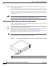
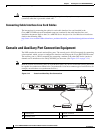
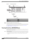
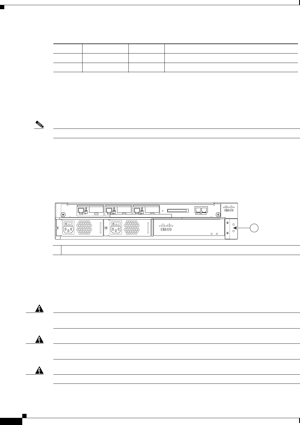
consist of a minimum #6 American Wire Gauge (AWG) stranded copper wire. See Figure 3-13 to
identify the ground lug location.
Figure 3-13 Cisco uBR7225VXR Ground Lug Location
Connecting Power
Following are the procedures for connecting AC-input power to your Cisco uBR7225VXR universal
broadband router.
Warning
High leakage current - earth connection essential before connecting to system power supply.
Statement 342
Warning
Care must be given to connecting units to the supply circuit so that wiring is not overloaded.
Statement
1018
Warning
Read the installation instructions before you connect the system to its power source.
Statement 1004
8 CD <— Carrier Detect (used for modem control)
20 DTR —> Data Terminal Ready (used for modem control only)
Table 3-3 Auxiliary Port Signals
Pin Signal Direction Description
1
Ground lug location
270534
uBR7225-VXR
uBR7225-VXR
1