


4-27
Cisco uBR7225VXR Universal Broadband Router Hardware Installation Guide
OL-17309-02
Chapter 4 Connecting the Cisco uBR7225VXR Router to the Cable Headend
Measuring the Upstream RF Signal
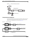
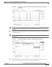
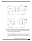
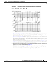
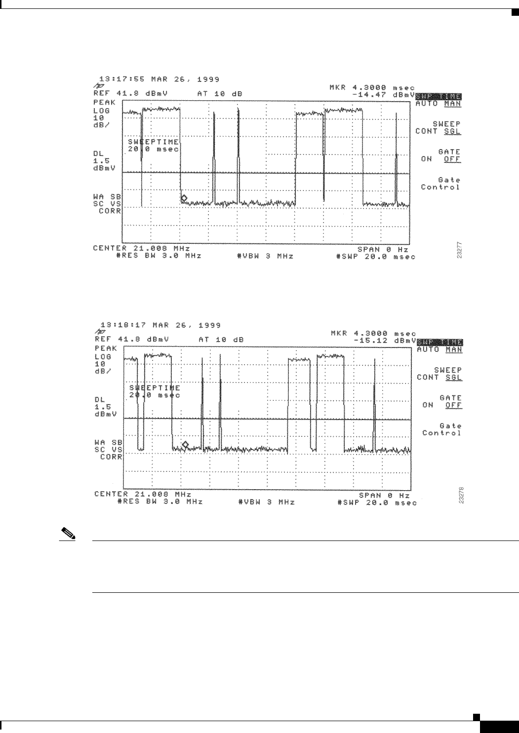
Figure 4-31 Analyzing the Upstream RF Signal—Multiple Active Remote Cable Modems (A)
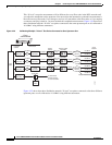
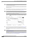
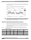
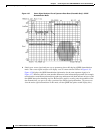
Figure 4-32 Analyzing the Upstream RF Signal—Multiple Active Remote Cable Modems (B)
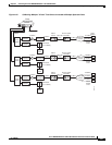
Note When viewing the upstream RF signal on your spectrum analyzer, two ping packet returns (for example,
from remote cable modems A and B) can be so close together that they appear to be one rather large
packet with a slight jump or decline in amplitude halfway through the measurement. This is an indication
that the upstream is 100 percent occupied during this time.
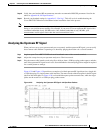
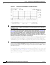
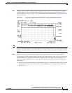
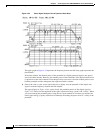
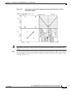
Figure 4-33 shows an upstream RF signal from a remote cable modem in a “real-life” scenario including
outside plant noise. Notice the relatively tall spike at the very left edge of the ping packet return. This
spike is mainly additive noise associated with an upstream RF signal mired by excessive amounts of
severe outside plant noise (as in this example). In addition, notice that the carrier-to-impulse noise ratio
measurement between the two diamond-shaped markers is only about 12 dB. (A few other noise peaks
are even worse.)