


2-6
Cisco uBR7225VXR Universal Broadband Router Hardware Installation Guide
OL-17309-02
Chapter 2 Preparing the Cisco uBR7225VXR Router for Installation
Site Requirements
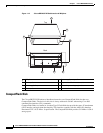
To provide airflow through the Cisco uBR7225VXR router, cooling air is drawn in through the air intake
vent on the right side of the chassis (when viewing the router from the front) and is exhausted through
the left side of the chassis. Keep the right and left sides of the chassis clear of obstructions and away
from the exhaust of other equipment.
Note The Cisco uBR7225VXR router is suitable for installation in Network Telecommunication Facilities and
locations where the National Electrical Code (NEC) applies. The Cisco uBR7225VXR router is not
intended for installation in outside plant (OSP) locations.
Site Configuration: Maintaining Normal Operation
Planning a proper location for the Cisco uBR7225VXR universal broadband router and the layout of
your equipment rack or wiring closet are essential for successful system operation. Equipment placed
too close together or inadequately ventilated can cause system overtemperature conditions. In addition,
chassis panels made inaccessible by poor equipment placement can make system maintenance difficult.
Following are precautions that can help avoid problems during installation and ongoing operation.
General Precautions
Follow these general precautions when planning your equipment locations and connections:
• Use the show environment command regularly to check the internal system status. The
environmental monitor continually checks the interior chassis environment; it provides warnings for
high temperature and maximum and minimum voltages and creates reports on any occurrences. If
warning messages are displayed, take immediate action to identify the cause and correct the
problem.
• We recommend keeping the Cisco uBR7225VXR router off the floor and out of any area that tends
to collect dust, excessive condensation, or water.
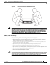
• Follow ESD prevention procedures to avoid damage to equipment. Damage from static discharge
can cause immediate or intermittent equipment failure.
Table 2-1 Specifications for Operating and Nonoperating Environments
Specification Minimum Maximum
Temperature, ambient operating 32
o
F (0
o
C) 104
o
F (40
o
C)
Temperature, ambient nonoperating and storage –4
o
F (–20
o
C) 149
o
F (65
o
C)
Humidity, ambient (noncondensing) operating 10% 90%
Humidity, ambient (noncondensing) nonoperating
and storage
5% 95%
Altitude, operating and nonoperating Sea level 10,000 feet (3,050 meters)
Vibration, operating 5 to 200 Hz, 0.5 g (1 oct./min.) –
Vibration, nonoperating 5 to 200 Hz, 1 g (1 oct./min.)
200 to 500 Hz, 2 g (1 oct./min.)
–