


3-15
Cisco uBR7225VXR Universal Broadband Router Hardware Installation Guide
OL-17309-02
Chapter 3 Installing the Cisco uBR7225VXR Router
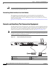
Console and Auxiliary Port Connection Equipment
Before connecting a terminal to the console port, configure the terminal to match the
Cisco uBR7225VXR router console port as follows:
• 9600 baud
• 8 data bits
• No parity
• 1 stop bit (9600 8N1)
You need an RJ-45 console cable to connect the terminal to the console port. After you establish normal
universal broadband router operation, you can disconnect the terminal.
You must supply your own interface cable between the auxiliary port and the equipment you are
connecting. For console and auxiliary port pinouts, refer to the “Console Port Signals” section on
page 3-15 and the “Auxiliary Port Signals” section on page 3-15.
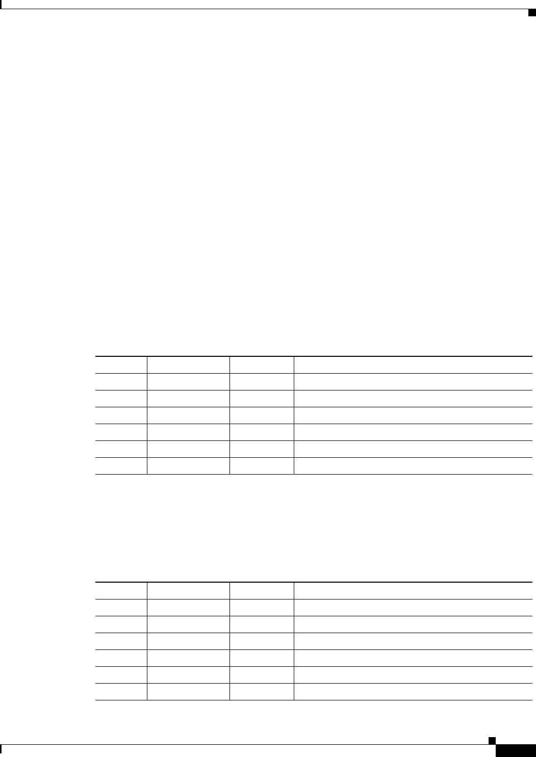
Console Port Signals
Both Data Set Ready (DSR) and Data Carrier Detect (DCD) signals are active when the system is
running. The Request To Send (RTS) signal tracks the state of the Clear To Send (CTS) input. The
console port does not support modem control or hardware flow control. Table 3-2 lists the signals used
on the console port. The console port requires a straight-through EIA/TIA-232 cable.
Auxiliary Port Signals
Table 3-3 lists the signals used on the auxiliary port. The auxiliary port supports hardware flow control
and modem control.
Table 3-2 Console Port Signal
Pin Signal Direction Description
1 GND – Ground
2 TxD <— Transmit Data
3 RxD —> Receive Data
6 DSR —> Data Set Ready (always on)
7 GND – Ground
8 DCD —> Data Carrier Detect (always on)
Table 3-3 Auxiliary Port Signals
Pin Signal Direction Description
2 TxD —> Transmit Data
3 RxD <— Receive Data
4 RTS —> Request To Send (used for hardware flow control)
5 CTS <— Clear To Send (used for hardware flow control)
6 DSR <— Data Set Ready
7 Signal Ground – Signal Ground