


4-23
Cisco uBR7225VXR Universal Broadband Router Hardware Installation Guide
OL-17309-02
Chapter 4 Connecting the Cisco uBR7225VXR Router to the Cable Headend
Measuring the Upstream RF Signal
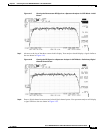
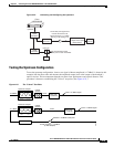
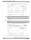
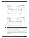
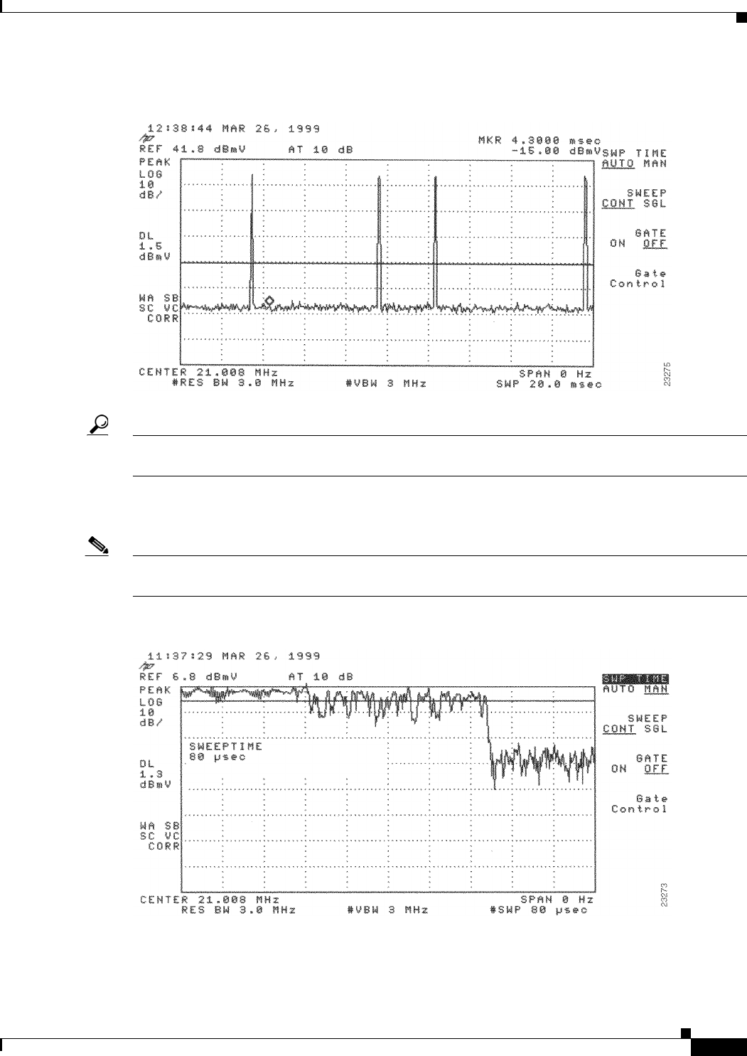
Figure 4-26 Measuring the Upstream RF Signal—Setting the Resolution and Video Channel
Bandwidth
Tip The horizontal line passing through the center of the spectrum analyzer display in Figure 4-26 is the
trigger line.
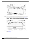
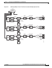
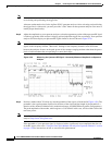
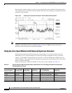
Step 6 Set the sweep value to 80 microseconds. Your spectrum analyzer should display a signal similar to the
one shown in Figure 4-27.
Note Be sure that your particular spectrum analyzer is capable of supporting sweep times as short as 80
microseconds.
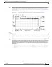
Figure 4-27 Measuring the Upstream RF Signal—Setting the Sweep Time Period
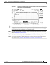
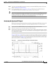
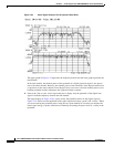
Step 7
Position the trigger line on the spectrum analyzer so that it is roughly in the middle (approximately
halfway between the highest and lowest portions) of the upstream RF signal.