


1-15
Cisco uBR7225VXR Universal Broadband Router Hardware Installation Guide
OL-17309-02
Chapter 1 Cisco uBR7225VXR Overview
Hardware Component Descriptions
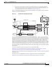
Temperature sensors on the network processing engine monitor the internal air temperature and send
warning messages when the internal air temperature approaches a specified threshold. If the internal
temperature exceeds the specified threshold, the system environmental monitor shuts down all internal
power to prevent equipment damage from excessive heat.
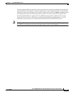
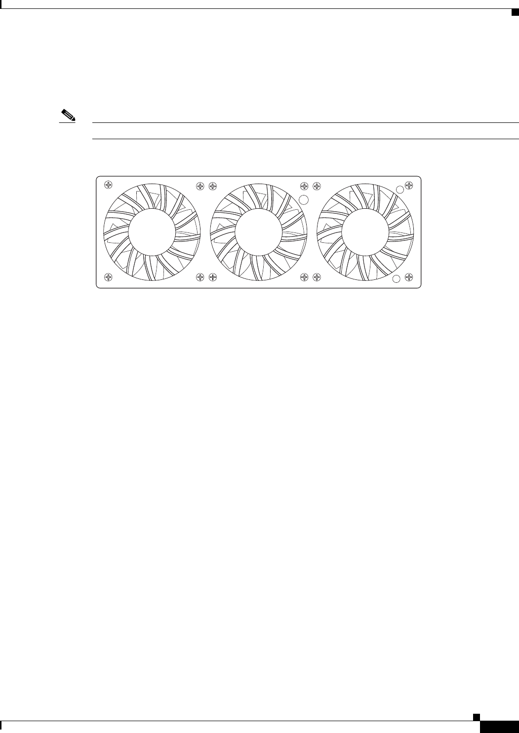
Note The Cisco uBR7225VXR router fan tray is not a field-replaceable unit.
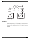
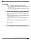
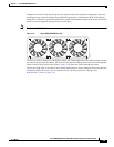
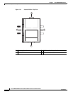
Figure 1-9 Cisco uBR7225VXR Fan Tray
The fan tray draws cooling air in through the intake vent on the right side of the chassis (when viewing
the router from the front) and moves the air across the internal components and sends it out through the
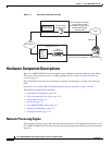
exhaust vent on the left side of the chassis. Figure 1-10 shows the airflow through the router.
The left and right sides of the chassis must remain unobstructed to ensure adequate airflow and prevent
overheating inside the chassis; we recommend at least 3 inches of clearance. (See the “Site
Requirements” section on page 2-5.)
270537