


4-19
Cisco uBR7225VXR Universal Broadband Router Hardware Installation Guide
OL-17309-02
Chapter 4 Connecting the Cisco uBR7225VXR Router to the Cable Headend
Connecting and Configuring the Upstream
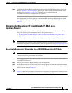
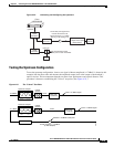
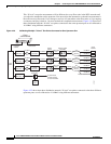
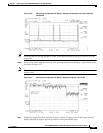
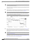
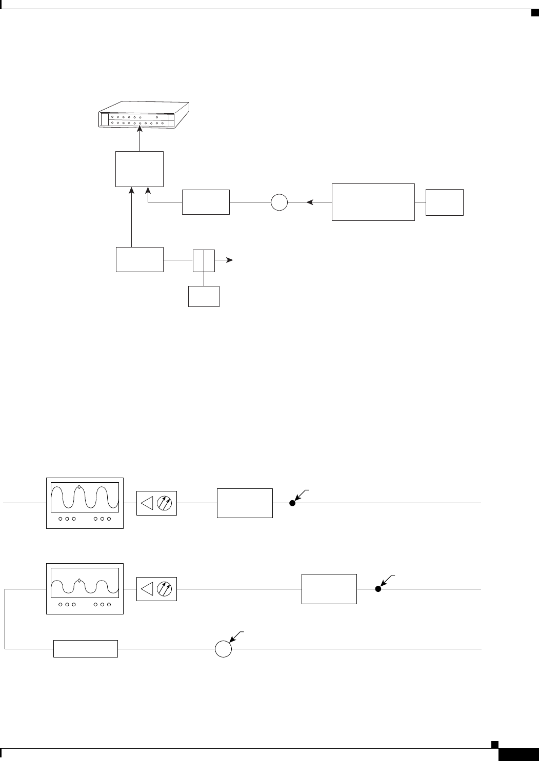
Figure 4-22 Connecting and Configuring the Upstream
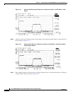
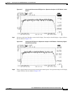
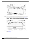
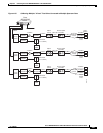
Testing the Upstream Configuration
To test the upstream configuration, insert a test signal of known amplitude (+17 dBmV is shown in this
example) into the fiber node and measure the amplitude output level at the output of the headend’s
optical receiver. This measurement depends on return laser performance and optical distance. This
procedure is known as establishing the “X-level” test point. (See Figure 4-23.)
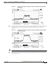
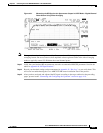
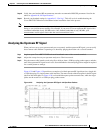
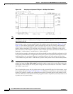
Figure 4-23 The “X-level” Test Point
Cisco
uBR7225VXR
271676
Upstream
Optical
receiver
To downstream forward
test point on laser transmitter
40 dB
attenuator
2-way
splitter
(combiner)
10 dB
attenuator
Optional attenuator
to adjust X-level point
measurement
X-level test point signal level
must be the same for all
optical receivers (+/- 0.5 dB),
See Fig. 4-36 and Fig 4-37
X
Cable
modem
LH
C
Diplex filter
14045
Spectrum analyzer
Optical
receiver
Fiber node
0.5 milliwatt
Fiber node
1.0 milliwatt
Spectrum analyzer
Optical
receiver
1dB attenuator
+11 dBmV
X-level test point = +10 dBmV
(in this example)
30 km
10 km
+17 dBmV
Insert +17 dBmV signal
X
Measure +10 dBmV at this point
Insert +17 dBmV signal