


4-38
Cisco uBR7225VXR Universal Broadband Router Hardware Installation Guide
OL-17309-02
Chapter 4 Connecting the Cisco uBR7225VXR Router to the Cable Headend
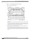
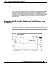
Measuring the RF Signal at the Forward Test Point on a Laser Transmitter
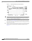
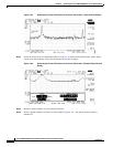
Figure 4-45 Downstream Forward Test Point on the Laser Transmitter—Video Channel Display
Step 3
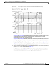
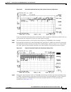
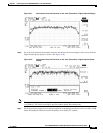
Select the carrier level (or amplitude) function. Figure 4-46 shows the detailed display of the analog
carrier level and frequency screen for the channel 48 (in this example).
Figure 4-46 Downstream Forward Test Point on the Laser Transmitter—Detailed Video Channel
Display
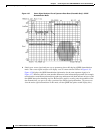
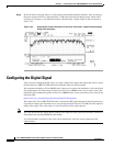
Step 4
Return to the main menu on your spectrum analyzer.
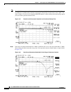
Step 5 Select a digital channel to measure. In the example in Figure 4-47, the digital channel shown is
channel 50.