


4-16
Cisco uBR7225VXR Universal Broadband Router Hardware Installation Guide
OL-17309-02
Chapter 4 Connecting the Cisco uBR7225VXR Router to the Cable Headend
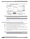
Measuring the Downstream RF Signal
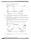
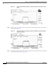
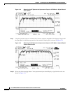
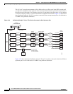
Figure 4-19 Measuring the RF Signal at the Upconverter Output in CATV Mode—Digital Channel
Power Screen
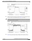
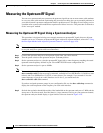
Step 9
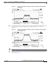
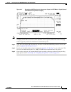
Using the spectrum analyzer’s reference level control, adjust the amplitude of the displayed signal until
the signal peak is within the top graticule of the analyzer’s display grid, as shown in Figure 4-20.
Figure 4-20 Measuring the RF Signal at the Upconverter Output in CATV Mode—Adjusted Digital
Channel Power Screen
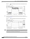
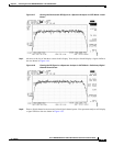
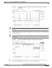
Step 10
Select the video averaging feature. Your spectrum analyzer should display a signal similar to the one
shown in Figure 4-21.