


4-8
Cisco uBR7225VXR Universal Broadband Router Hardware Installation Guide
OL-17309-02
Chapter 4 Connecting the Cisco uBR7225VXR Router to the Cable Headend
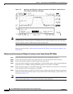
Measuring the Downstream RF Signal
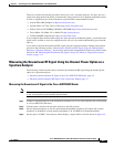
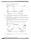
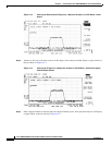
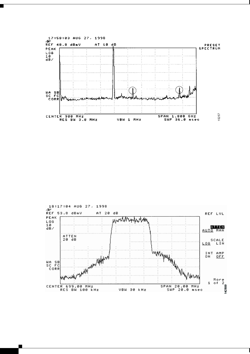
Figure 4-6 Overloaded Spectrum Analyzer Input
Step 4
Set the input of the upconverter to a digital QAM signal and the output level to the manufacturer’s
recommended settings. Typical output amplitudes range from +50 to +58 dBmV, although DOCSIS
specifies +61 dBmV.
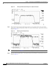
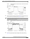
Step 5 Set the spectrum analyzer to view the RF signal at the center frequency you selected for your headend.
In this example, the RF center frequency is 699 MHz. Set your span to 20 MHz. Finally, set your channel
spacing and your channel bandwidth to 6 MHz.
If the RF signal is causing an overload condition on the spectrum analyzer input, your analyzer might
display a signal similar to the one shown in Figure 4-7. The sloping of the lines at the sides of the signal
indicates a false reading.
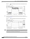
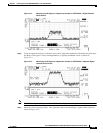
Figure 4-7 Measuring the RF Signal at the Upconverter Output—Overload Condition
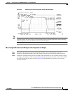
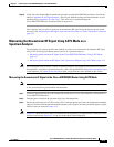
Step 6
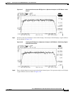
If you add attenuation to the input to the spectrum analyzer you can correct the overload condition as
shown in Figure 4-8.