


TECHNICAL DESCRIPTION
1 - 11
ETC303(1) BINOS E e (2.0) 02/2007
Rosemount Analytical
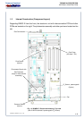
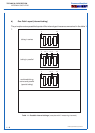
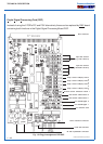
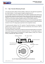
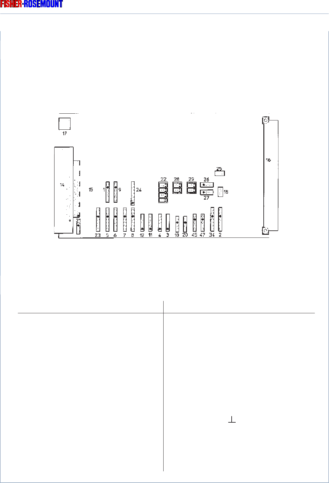
Fig. 1-8: Plug pin assignment PCB PIC
The plugs shown in Fig. 1-20 are used as follows:
Plug No. used
34 Chopper 1 (channel 1+2)
2 Chopper 2 (channel 3+4)
47 Flow sensor 1
45 Flow sensor 2
20 Temperature sensor 1 (chopper 1)
10 Temperature sensor 2
3 Source channel 4
4 Source channel 3
11 Source channel 2
12 Source channel 1
8 Detector channel 4
7 Detector channel 3
6 Detector channel 2
5 Detector channel 1
23 Detector channel 5 (O
2
)
Plug No. used
1 Pressure senor 1
9 Pressure senor 2
24 PCB OKI (P2) Flow sensor 3
PCB OKI (P1) Flow sensor 4 (P1)
or
PCB OKI (P4) Temperature sensor 3
PCB OKI (P3) Temperature sensor 4
21.2 Proof peak (test peak) channel 1
21.3 Ground ( )
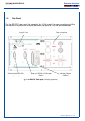
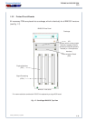
PIC
The PIC card (Physics Interface Card) supplies the photometer components and the individual
sensors with the individual required operating voltages and transmits all measuring signals to
the signal processing unit PSV.
PCB
1
2
3