


MEASURING PRINCIPLE
2 - 4
ETC00303(1) BINOS E e (2.0) 11/00
Rosemount Analytical
IR MEASUREMENT
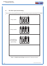
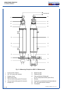
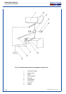
When the IR radiation passes through the reference side of the analysis cell into the detector,
no pre-absorption occurs. Thus, the gas inside the absorption chamber is heated, expands and
some of it passes through the flow channel into the compensation chamber.
When the IR radiation passes through the measurement side of the analysis cell into the
detector, a part of it is absorbed depending on gas concentration. The gas in the absorption
chamber, therefore, is heated less than in the case of radiation coming from the reference side.
Now absorption chamber gas become colder, gas pressure in the absorption chamber is
reduced and some gas of compensation chamber passes through the flow channel into the
absorption chamber.
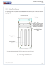
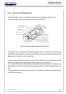
The flow channel geometry is designed in such a way that it hardly impedes the gas flow by
restriction. Due to the radiation of chopper wheel, the different radiation intensities lead to
periodically repeated flow pulses within the detector.
The Microflow sensor evaluates these flow pulses and converts them into electrical voltages.
The electronics, which follow, evaluate the signals and convert them into the corresponding
display and output format.
The high chopping rate used, permits using a portion of the perimeter of the chopper wheel
for responsivity recalibration. A special pattern of the chopper wheel illuminates the detector
with about 1/4 and then with about 3/4 of the total light intensity creating a so-called "proof
peak". Thus, with any chopper rotation, an automatic gain control is used for automatic span
(sensitivity) control. The result is a high long-term stability of sensitivity.
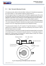
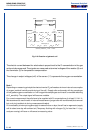
2.1.2 Interference Filter Correlation (IFC Principle)
With the IFC method the analysis cell is alternately illuminated with filtered IR light concen-
trated in one of two spectrally separated wave length ranges. One of these two wavelength
bands is chosen to coincide with an absorption band of the sample gas and the other is chosen
such that none of the gas constituents expected to be encountered in practice absorbs
anywhere within the band.
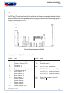
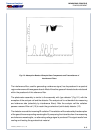
The spectral transmittance curves of the interference filters used in the BINOS and the spectral
absorption of the gases CO and CO
2
are shown in Fig. 2-3. It can be seen that the absorption
bands of these gases each coincide with the passbands of one of the interference filters.