


14 - 1
LEAK TESTING
ETC00303(1) BINOS E e (2.0) 11/00
Rosemount Analytical
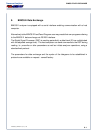
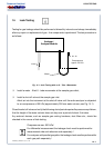
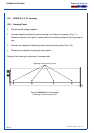
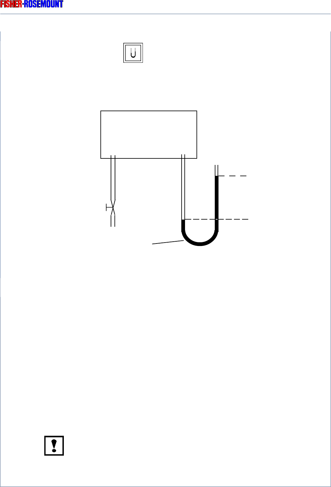
Fig. 14-1: Leak Testing with an U - Tube - Manometer
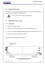
❍ Install a water - filled U - tube manometer at the sample gas outlet;
❍ Install a shut-off valve at the sample gas inlet.
Admit air into the instrument at the shut-off valve until the entire analyzer is subjected
to an overpressure of 50 hPa (approximately 500 mm water column; see Fig. 14-1).
Close the shut-off valve and verify that following a brief period required for pressure equilibrium,
that the height of the water column does not drop over a period of about 5 minutes.
Any external devices, such as sample gas cooling hardware, dust filters etc., should be
checked in the course of leak testing.
Overpressure max. 500 hPa !
For differential measurement the leakage check must be performed for
measurement side and reference side separately !
For analyzers with parallel gas paths the leakage check must be performed for
each gas path separately !
14. Leak Testing
Testing for gas leakage should be performed at bimonthly intervals and always immediately
after any repair or replacement of gas - line components is performed. The test procedure is
as follows:
Analyzer /
Analyzer Module
Overpressure
approx. 50 hPa
Valve
Water