MEASURING PRINCIPLE
2 - 5
ETC00303(1) BINOS E e (2.0) 11/00
Rosemount Analytical
Wave Length [nm]
4400 460042004000 48003000 3200 3400 3600 3800 5000 5200 5400 5600 5800 6000
CO
2
CO
Interference
Filter
Absorption band
HC
CO
2
CO
18 36 54 72 900
Transmittance [%]
9075604530150
Transmittance [%]
IR MEASUREMENT
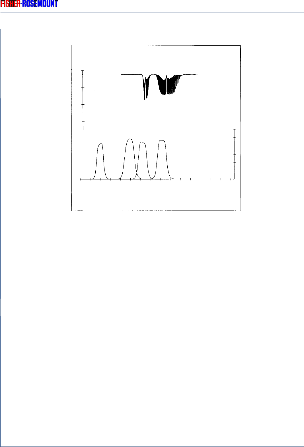
Fig. 2-3: Absorption Bands of Sample Gase Components and Transmittance of
Interference Filters
The interference filter, used for generating a reference signal, has its passband in a spectral
region where none of these gases absorb. Most of the other gases of interest also do not absorb
within the passband of this reference filter.
The photometer assembly is similar to the assembly with “gas detector” (Fig. 2-1) with the
exception of the analysis cell and the detector. The analysis cell is not devided into measuring
and reference side (selectivity by interference filters). After the analysis cell the radiation
passes a second filter cell (10) to reach the pyroelectrical (solid-state) detector (12).
The detector records the incoming IR radiation. This radiation will be reduced by the absorption
of the gas at the corresponding wavelengths. By comparing the intensities from the measuring
and reference wavelengths, an alternating voltage signal is produced. This signal results from
cooling and heating the pyroelectrical material.
Reference


