


17 - 1
REPLACEMENT AND CLEANING OF PHOTOMETRIC COMPONENTS
ETC00303(1) BINOS E e (2.0) 02/2007
Rosemount Analytical
17. Replacement and Cleaning of Photometric Components
The housing has to be opened for checking the electrical connections and for replacement or
cleaning of any of the components of the equipment.
Be sure to observe the safety measures, Item 5. and 6. especially !
17.1 Removal of the Photometer Assembly
Open the housing (cf. Section 15).
Disconnect all electrical connections between photometer assembly and electronic unit
(pcb PIC or DSP) and remove all gas lines from the photometer assembly if necessary.
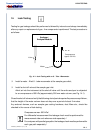
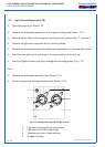
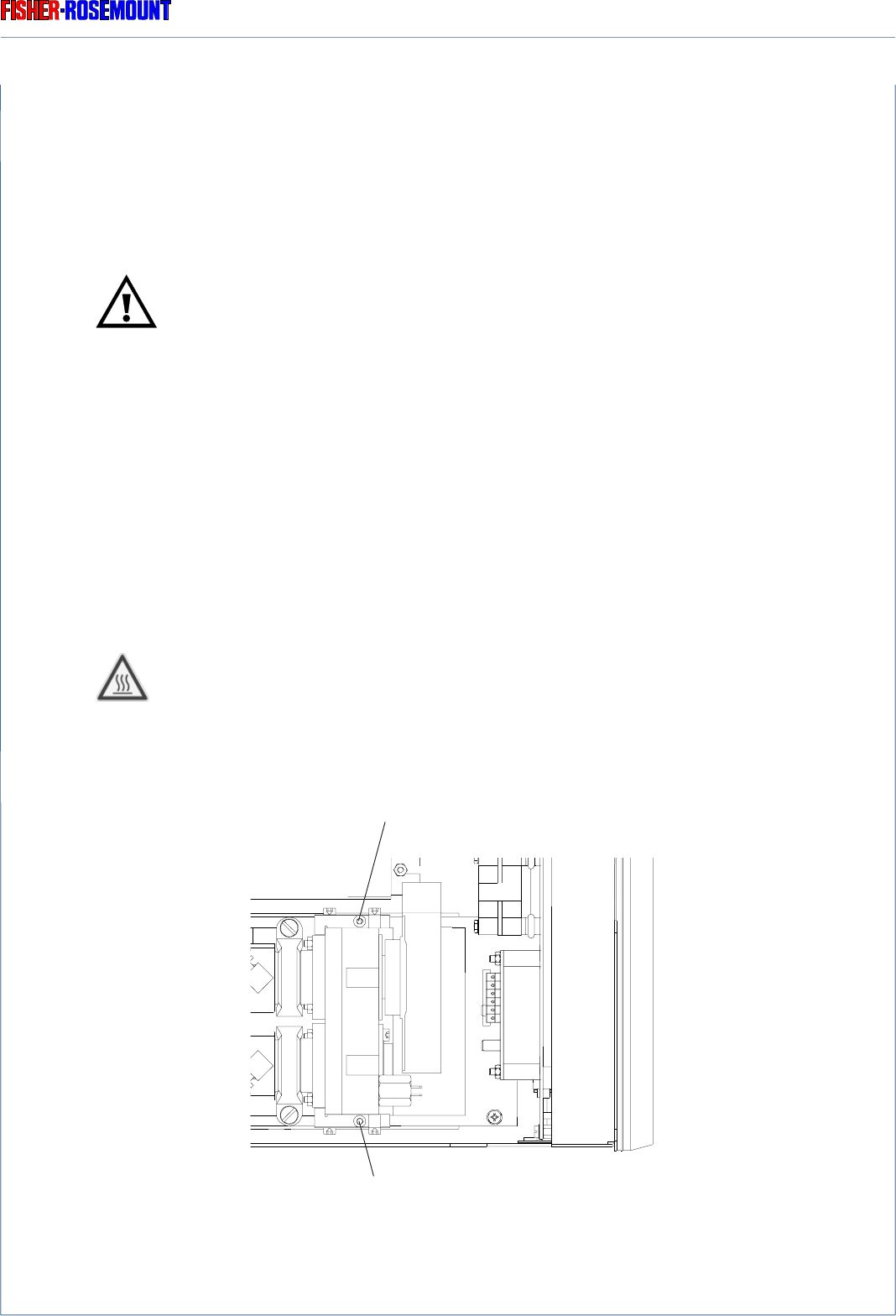
Unscrew both the hexagonal screws shown in Fig. 17-1.
Depending on photometer or analyzer/analyzer module there could be exist hot
components !
Remove the photometer assembly to top of analyzer housing as a unit.
REMOVAL OF THE PHOTOMETER ASSEMBLY
Fig. 17-1: Photometer Assembly, example
(Top view, detail)
hexagonal screw
hexagonal screw