


CHECK AND REPLACEMENT OF ELECTROCHEMICAL OXYGEN SENSOR
18 - 5
ETC00303(1) BINOS E e (2.0) 11/00
Rosemount Analytical
BASIC CONDITIONS FOR SENSOR
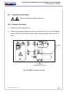
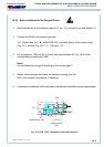
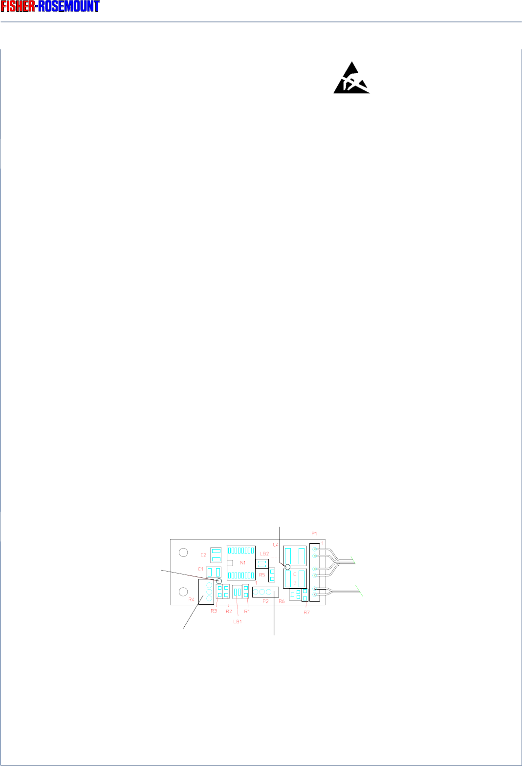
Fig. 18-3: PCB “OXS”, assembled, horizontal projection
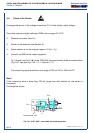
18.2.4 Basic conditions for the Oxygen Sensor
❍ Admit ambient air for the analyzer (approx. 21 Vol. - O
2
) and switch on (see Section 6.).
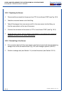
❍ Connect the DVM to the measuring points
Tp 1 (Signal) and Tp 2 (
⊥⊥
⊥⊥
⊥ ) of the PCB OXS, mounted directly at the sensor block
(Fig. 18-1, see also Fig. 18-2, 1-3, 1-16a and 1-17).
❍ Set the signal to 1000 mV DC (± 5 mV) with potentiometer R4 (Fig. 18-3) of the
corresponding circuit board “OXS”.
Note !
It is not allowed to change this setting for this sensor again !
❍ Switch off the analyzer and close the analyzer housing (see 15.).
Built-in the module into platform if necessary.
❍ A complete re-calibration of the instrument must be performed after a sensor replacement.
Connection
oxygen sensor
(“P2”)
Tp 1
Tp 2
Potentiometer “R4”