


MEASURING PRINCIPLE
2 - 3
ETC00303(1) BINOS E e (2.0) 11/00
Rosemount Analytical
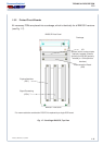
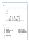
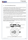
2.1.1 Opto - Pneumatic Measuring Principle
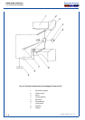
In the opto-pneumatic method, a thermal radiator ( heating coil in the light source) generates
the infrared radiation (1) which passes through the chopper wheel (3).
Due to the special shape of the chopper wheel, the IR radiation passes through a filter cell (5)
and alternately reaches the measuring side (8) and reference side (9) of the analysis cell [(7)
separated in the middle into two halves by an internal separating wall] with equal intensity.
The filter cell (5) screens interfering radiation areas out of the radiation spectrum.
After the analysis cell the radiation passes a second filter cell (10) and reaches the gas detector
(12), which compares the IR radiation intenisities from measuring side and reference side and
converts it into an AC voltage signal proportional to their respective intensity.
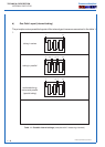
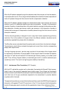
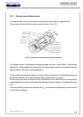
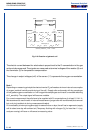
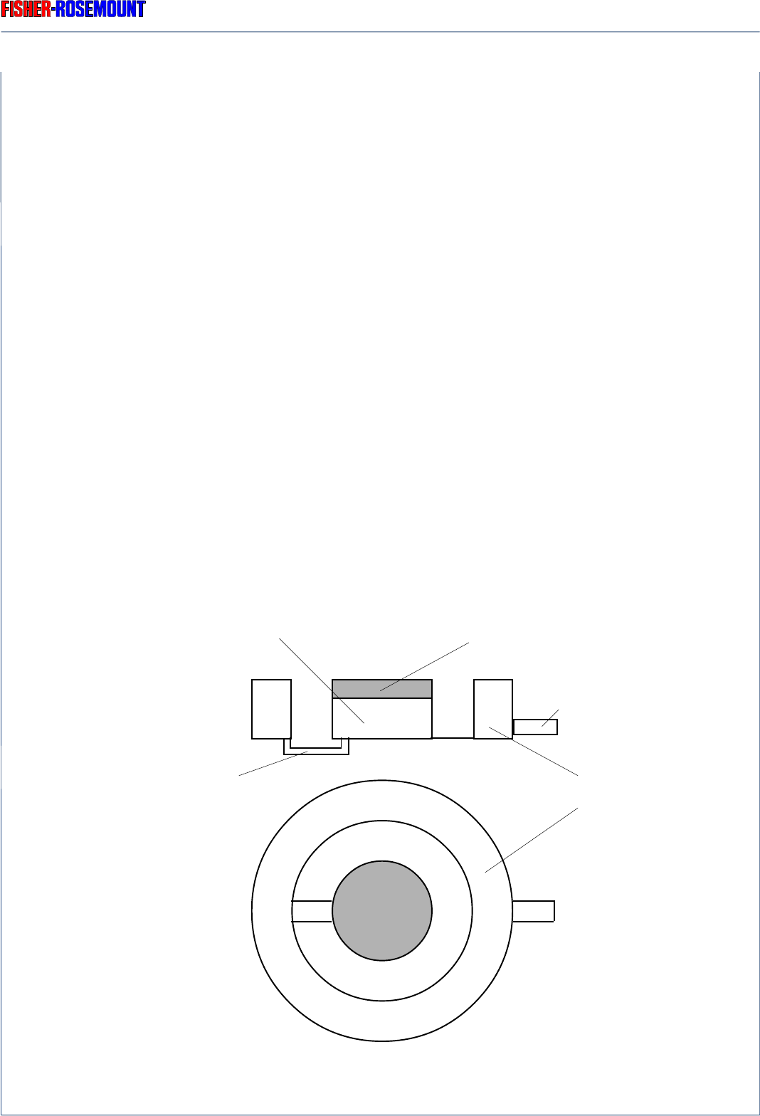
The opto-pneumatic detector (Fig. 2-2) consists of 2 gas-filled chambers, an absorption
chamber and a compensation chamber which are connected by a flow channel in which a
Microflow filament sensor is mounted.
In principle the detector is filled with the infrared active gas to be measured and is only sensitive
to this distinct gas with its characteristic absorption spectrum. The absorption chamber is
sealed with a window which are transparent for infrared radiation [usually CaF
2
(Calcium
fluoride), sometimes BaF
2
(Barium fluoride)].
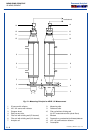
Fig. 2-2: Principle Design of the Opto-Pneumatic Gas Detector
Gas intake connection
Absorption chamber
CaF
2
/ BaF
2
window
Compensation chamber
IR MEASUREMENT
Flow channel with
Microflow sensor