


Rev.A Interfaces Appendix 1-1
Developer's Guide SR-600
Confidential
Appendix 1
Interfaces
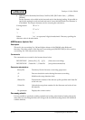
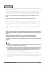
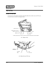
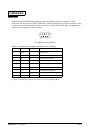
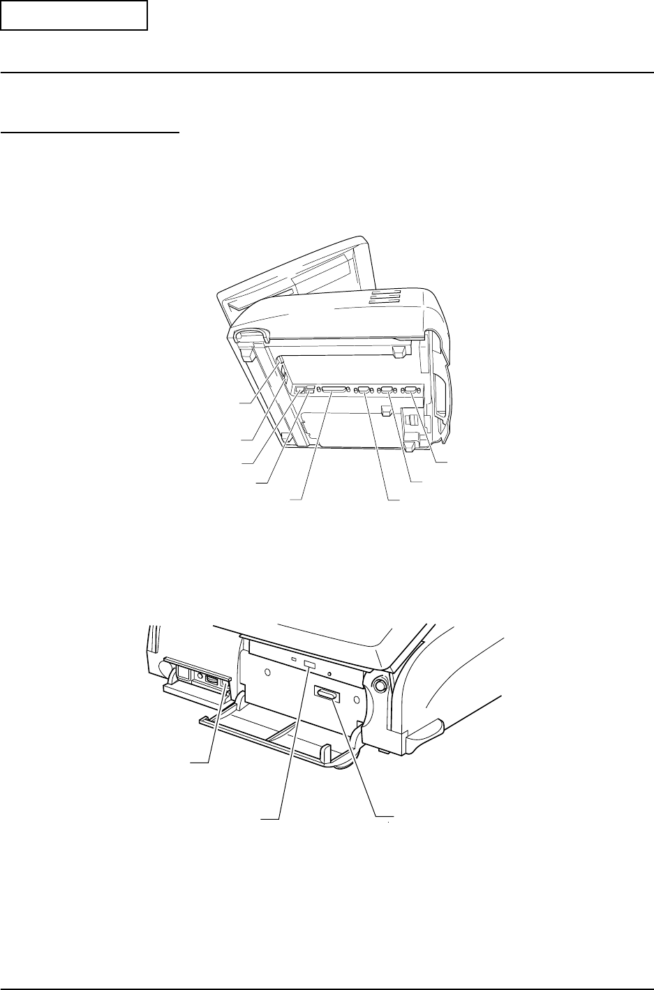
Connector Location
Connectors are on the bottom of the base unit and inside of the switch cover and CD cover.
Connector layout is shown in the figure below.
* CRT and drawer kick connector is used if the optional CRT/drawer board is installed.
A1-1 Bottom View
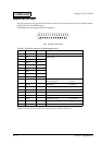
A1-2 Switch Cover/CD Cover
COM1
COM2
COM3
LPT
USB Connector
Ethernet Connector
Drawer Kick Connector
*CRT Connector
FDD
Connector
CD-ROM
Drive
K/B Mouse
Connector