


3-6 BIOS Setup Rev.A
Confidential
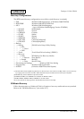
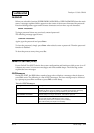
CHIPSET FEATURES SETUP
It sets the items that rely on the chipset situated on the motherboard, such as the memory, the
bus timing and the system temperature. As the optimum parameters are normally set by
executing [LOAD SYSTEM DEFAULT], these settings need not be changed.
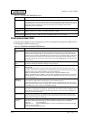
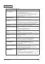
Table 3-4 CHIPSET FEATURES SETUP Menu
Items Description
SDRAM RAS to
CAS Delay
It sets the Delay time after the SDRAM RAS to move to CAS. It increases Memory Access as it
reduces time interval.
SDRAM RAS
Precharge Time
This is a SDRAM version of DRAM RAS Precharge Time. It sets the CPU clock assigned for RAS
signal to store the required electric charge before the SDRAM reflesh. It increases accessibility
as it reduces value, but it may cause problems in Reflesh and loose contents of the memory if
the value is set too low.
SDRAM CAS
Latency
It sets the value of CAS Waiting Time Clock . It increases accessibility as it reduces this value.
DRAM Data
Integrity Mode
It increases reliability of Data.
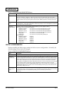
System BIOS
Shadow
It sets whether to copy (shadowing) or not copy the system BIOS code between F0000h and
FFFFFh into the
main memory. Normally set at [Disabled].
Enabled: Shadowing
Disabled: Non Shadowing
Performance will be improved with operating systems that perform the BIOS call, such as DOS,
Win 95, 98 and 2000, by setting this parameter to [Enabled]. On the other hand, it must be set at
[Disabled] for WinNT, which does not perform the BIOS call.
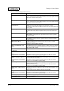
Video BIOS
Cacheable
It sets whether to cache (L2 cache) the shadowed video BIOS code.
Performance will be improved by setting this parameter to [Enabled].
Video RAM
Cacheable
It sets whether to cache (L2 cache) the shadowed video RAM (VRAM).
Performance will be improved by setting this parameter to [Enabled].
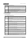
8Bit I/O
Recovery Time
It sets the 8-bit ISA timing. It is necessary to align the pace of CPU operations for bus I/O request
completion in order to ensure the speed is faster than the I/O bus. This stand-by time is known as
'recovery time.' This is usually one bus clock, but it is possible to increase this figure to stabilize
the system if the ISA bus device operations are unstable.
16Bit I/O
Recovery Time
It sets the 16-bit ISA timing. This is usually one bus clock, but it is possible to increase this figure to
stabilize the system if the ISA bus device operations are unstable.
PassiveRelease The settings related to the chipset's PCI-ISA bridge. As the response from the ISA bus device is
not good for CPU requests, the CPU will not be able to execute other processes while waiting
for the ISA bus response, and performance will consequently be lowered. In order to solve this
problem, an ISA/EISA cycle and a CPU-to-PCI cycle are triggered simultaneously in a function
added from PCI specification revision 2.1. This is normally set at [Enabled].
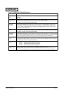
Delayed
Transaction
This function is only valid for chipsets mounted with a 32-bit post write buffer, a function added
from PCI specification revision 2.1.
This function releases (passively) the PCI bus during ISA bus
access that consumes approximately 50 to 60 PCI clocks. In other words, bus master access is
possible from the PCI device during ISA bus access, and this increases performance. Normally
set at [Disabled].
CPU Temp High
Limit
It sets the High Limit of Thermal Throttling by hardware.
If the setting temperature is above the High Limit, It automatically changes the CPU to Low
Power Mode and decreases CPU temperature. If the temperature is set too low or the
temperature difference to Low Limit is too little, CPU speed changes frequently and the
performance may decrease. Also, it is necessary to set the higher temperature than the Low
Limit.