


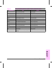
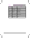
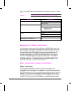
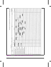

The major assemblies and subassemblies of the stapler are shown in Table
5-7.
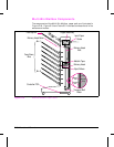
Mailbox with Stapler Operation
All communication and control of the Mailbox, the 2000-Sheet Input Tray,
and the Stapler is through the External Paper Handling Controller (EPH)
PCA mounted in the Formatter Assembly. These instructions are sent to
the stapler controller PCA located in the lower part of the stapling unit.
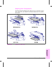
The main components of the stapler are listed in Table 5-6. Power is
provided to the stapler by the Multi-Bin Mailbox/Mailbox With Stapler
external 24Vdc power supply through the CLINK cable. The stapler is
mounted in the Multi-Bin Mailbox/Mailbox With Stapler, replacing the
three top output bins. It handles letter and A4 sizes plain paper. The
stapler can staple up to a maximum of 20 sheets.
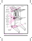
Main Functional Cycles of the Stapler
Paper Feed Cycle
The Stapling Bed Assembly receives the paper from the Multi-Bin
Mailbox/Mailbox With Stapler Head assembly. The IR Sensor detects when
the paper arrives in the stapler. The Retainer (a shaft holding two rubber
flexible fingers or anti-curl fingers) rotates once to apply pressure down and
backward. This action forces the paper to register against the rear wall of
the Stapling Bed, as well as reduces paper curl. The Registration Pusher
(located in the right side of the Top Assembly) registers the paper against
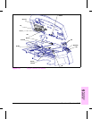
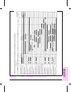
Major Assembly Subassemblies
Stapling Bed Assembly Retainer Assembly
Sliders Assembly
Top Cover Assembly Stapler Assembly
Rack Assembly
Registration Pusher
Off-Set Pusher
Exit Flap Assembly
Housing Output Bin
Bin Full Sensor Actuator
Wire Frame
Stapling Unit Controller PCA
N/A
Table 5-7
Major Assemblies and Subassemblies of the Stapler
5-36 Functional Overview