


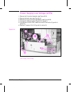

PCA, Output Paper Sensor
1 Remove the following components in the order listed:
• Toner Cartridge
• Formatter Assembly (see Figure 6-24)
• AC Access Cover (see Figure 6-3)
• Top Cover (see Figure 6-8)
• Back Cover (see Figure 6-4)
• Fan 3 and Housing Assembly (see Figure 6-20)
• HVPS (see Figure 6-40)
• DC Controller PCA (see Figure 6-32)
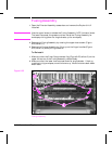
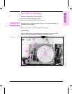
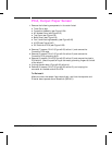
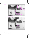
2 Remove (7) screws, CH101 (Figure 6-33, callout 1) and remove the
Formatter PCA cage.
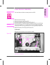
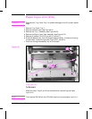
3 Remove (5) screws, CH101 (Figure 6-34, callout 2) and remove the
Formatter PCA grounding strip.
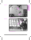
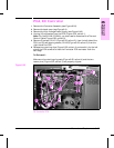
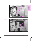
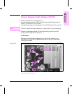
4 Remove (3) screws, CH102 (Figure 6-35, callout 3) and remove the plastic
PCA shield. (Note the positioning of the metal grounding fingers at the left
of the shield.)
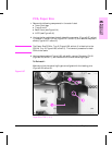
5 Unplug the connector (Figure 6-36, callout 4).
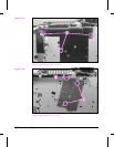
6 Remove (2) screws, CH101 (Figure 6-36, callout 5), and unplug the
connector on the back side of the PCA.
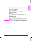
To Reinstall:
Make sure that the sensor flags rotate freely, and that the top cover and
Diverter doors operate the microswitch (SW1401).
6-48 Removal and Replacement