


RESTRICTED USE ONLY Fargo Electronics, Inc.
DTC400/DTC300/DTC300M Card Printer Service Manual (Rev. 1.3)
8
-
57
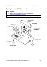
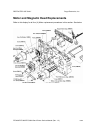
Board, Interface and Printhead Replacements
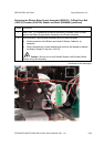
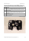
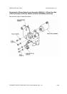
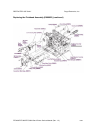
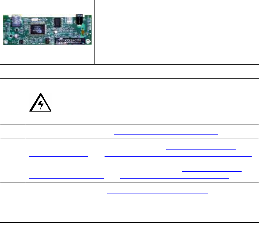
Replacing the Power/Communication Board (A000368)
Refer to Drawing D900115.
Tools Needed: Torx T-10 Screwdriver, Phillips Head
Screwdriver.
Parts Needed: Power/Communication Board A000368
Estimated Repair Time: 20 minutes.
Steps Procedure
1
Caution: Turn off the Printer and unplug the power cord from the
Printer.
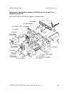
2 Remove the Rear Cover. See Replacing the Rear Cover (D900066).
3 Remove the Input Door and Right End Cap. See Replacing the Input Door
Assembly (D900148). See Replacing the Right End Cap (D900065-01 and –02).
4 Remove the Card Output Door and Left End Cap. See Replacing the Output
Door Assembly (D900092). See Replacing the Left End Cap (D900064).
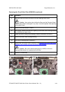
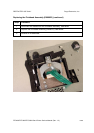
5 a. Remove the Input Tray. Replacing the Input Tray (D900097).
b. Use a No. 2 Phillips screwdriver to remove the two (2) screws (130984) that
secure the Left End Cap (D900064-01, DTC400; DTC900064-02, DTC300)
to the main assembly.
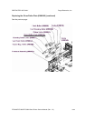
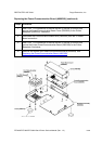
6 Remove the Printer Baseplate. See Replacing the Baseplate (D900000).
Continued on the next page