


4
4-24 TCP/IP Ethernet Communications User’s Manual – January 1996
GFK-1004B
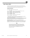
Assign Channel Status Vector (2000)
The Assign Channel Status Vector (ACSV) command specifies the location in local PLC
CPU reference table memory of the sixty-four (64) Channel Status bits. This command is
required for COMMREQ support when the Ethernet Interface has been configured by
Logicmaster 90-70 to be in MMS-ETHERNET configuration mode. If, however, the
Ethernet Interface has been configured in TCP/IP configuration mode, this command
must not be used. When in TCP/IP configuration mode, Logicmaster 90-70 configures the
location of the sixteen LAN Interface Status (LIS) bits as well as the sixty-four Channel
Status bits, and all eighty (80) status bits are updated once each PLC scan.
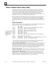
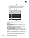
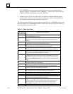
Example Command Block
Specify %T56 (in bit mode) as the starting location for the sixty-four Channel Status bits.
Return the COMMREQ Status (CRS) word in %AQ14.
Dec (Hex)
Word 1 00003 (0003) Length of Assign Channel Status Vector data block (3 words)
Word 2 00000 (0000) Always 0 (no-wait mode request)
Word 3 00012 (000c) Memory type of CRS word (%AQ)
Word 4 00013 (000d) CRS word address minus 1 (%AQ14)
Word 5 00000 (0000) Reserved
Word 6 00000 (0000) Reserved
Word 7 02000 (07d0) Assign Channel Status Vector command number
Word 8
Word 9
00074 (0040)
00056 (0038)
Memory type where to put Channel Status bits (%T)
Starting address of Channel Status bits
* Word 4 (CRS word address) is the only zero-based address in the Command Block.
Only this address requires subtracting 1 from the intended address.
(Word 7) Channel Command Number: The command parameter in Word 7 requests that
the sixty-four (64) bits of Channel Status be assigned to a local reference table address
(specified in Words 8 and 9). If the command is processed successfully, the CRS word
will indicate successful completion. From that point on, the Ethernet Interface will
update sixty-four bits at the specified location each time the status changes. This will
continue until either the channel is aborted or another ACSV command is issued.
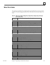
(Word 8) Memory Type: Words 8 and 9 specify the starting address in local PLC
memory for the sixty-four (64) bits of Channel Status. Word 8 specifies the memory type
(see Table 4-2).
(Word 9) Starting Address: Starting address to store the Channel Status bits.
Note
If both Word 8 and Word 9 are zero (0), this means “none”, which will
cause the Ethernet Interface to stop updating memory with the Channel
Status bits. If the address in Words 8 and 9 is valid, the Ethernet
Interface will update that memory location with 64 bits of information
each time one of those bits change.