


B
TCP/IP Ethernet Communications User’s Manual – January 1996B-2
GFK-1004B
Table B-1. Pinouts of the Serial Port
Pin Number Signal Description
1 Shield Chassis Ground (optional)
2 TXD Transmit Data (output)
3 RXD Receive Data (input)
7 Common Signal Ground
(all others) Unused
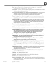
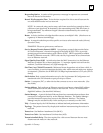
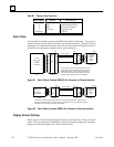
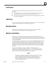
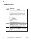
Serial Cable
A serial cable is needed to connect the GSM to the Ethernet Interface. The next two
figures illustrate typical cable connection of a personal computer. Figure B-1 shows
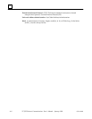
connections to a personal computer with a 25–pin serial port and Figure B-2 shows
connections to a personal computer with a 9-pin serial port..
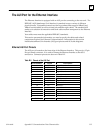
RS-232 CABLE
*
THE PINS AND CONNECTOR MAY BE DIFFERENT FOR
SOME COMPUTERS OR TERMINALS, BUT THE SIGNAL
NAMES WILL BE THE SAME. CONSULT THE MANUAL
FOR YOUR COMPUTER OR ASCII TERMINAL FOR THE
CORRECT SIZE CONNECTOR AND PIN NUMBERS.
3
2
*
PIN
*
25-PIN
MALE
25-PIN
SERIAL PORT
ON
PERSONAL
COMPUTER
25-PIN
FEMALE
2
3
a45181
PIN
9-PIN
MALE
ETHERNET
INTERFACE
MODULE
SERIAL
PORT
9-PIN
FEMALE
77
RXD
TXD
GND
TXD
RXD
GND
Figure B-1. Serial Cable to Connect GSM (25–Pin Connector) to Ethernet Interface
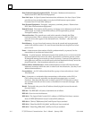
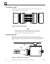
RS-232 CABLE
a45182
PIN
* 2
PIN
9-PIN
FEMALE
9-PIN
MALE
ETHERNET
INTERFACE
MODULE
SERIAL
PORT
*
THE PINS AND CONNECTOR MAY BE DIFFERENT FOR SOME COMPUTERS OR TERMINALS, BUT
THE SIGNAL NAMES WILL BE THE SAME. CONSULT THE MANUAL FOR YOUR COMPUTER OR ASCII
TERMINAL FOR THE CORRECT SIZE AND PIN NUMBERS.
9-PIN
MALE
9-PIN
SERIAL PORT
ON
PERSONAL
COMPUTER
9-PIN
FEMALE
2
3
7
TXD
RXD
GND
RXD
TXD
GND
* 3
* 5
Figure B-2. Serial Cable to Connect GSM (9–Pin Connector) to Ethernet Interface
Display Terminal Settings
When used as a local Station Manager terminal, set the terminal to “Wrap-Around”
mode. This prevents loss of information in the event a Station Manager command
response exceeds the display line width of the terminal.