


2
2-2 TCP/IP Ethernet Communications User’s Manual – January 1996
GFK-1004B
PUSH
SLIDE FROM
FRONT TO
LOCK: FROM
BACK TO
RELEASE
15–PIN
ETHERNET
CONNECTOR
MODEL 70
CMM 741
MODULE OK
ONLINE
STATUS OK
BATTERY
CONNECTIONS
INSTALL NEW
BATTERY BEFORE
UNPLUGGING OLD
BATTERY. USE
IC697ACC701
ON OR BLINK= OK
MODULE
IC697CCM741
LABEL
44A726758–117R01
Y
R
E
B
A
T
T
OPEN
REPLACEMENT
BATTERY
CONNECTOR
CURRENTLY
INSTALLED
BATTERY
CONNECTOR
RESTART
PUSHBUTTON
9–PIN
SERIAL
PORT
LEDS
GROUND
WIRE
DEFAULT
STATION
ADDRESS
LABEL
a44663
SERIAL
NUMBER
LABEL
SERIAL
PORT
RS–232
DTE
2 TX (OUT)
3 RX (IN)
7 GND
TRANSCEIVER
CABLE
WHEN RUNNING
DIAGNOSTICS
PUSH TO RESTART
LAN INTERFACE.
PUSH AND HOLD
TO REQUEST
LAN INTERFACE
DOWNLOAD. INOP
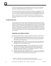
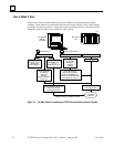
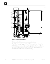
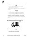
Figure 2-1. Ethernet Controller Board
The Ethernet Controller board has several user-accessible elements.
Three LEDs are located at the top of the board. The Restart pushbutton is located im-
mediately below the LEDs. The battery and battery holder is located to the right of the
LEDs. The battery connectors are located on the controller board between the Restart
button and the 9-pin connector to the serial port. The 15-pin connector, located beneath
the serial port and facing downward, is the transceiver port. The Default Station Ad-
dress label is affixed on the outside of the plastic housing.