


B
TCP/IP Ethernet Communications User’s Manual – January 1996B-4
GFK-1004B
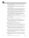
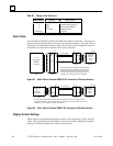
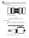
AUI (Transceiver Cable)
The figure below shows a typical cable configuration to connect the AUI port of the
Ethernet Interface to an external transceiver.
a44668
MMS-ETHERNET
PIN
15- PIN
MALE
TRANSCEIVER
PIN
15- PIN
MALE
15- PIN
FEMALE
SHELL
15- PIN
FEMALE
1
2
3
4
5
6
7
8
9
10
11
12
13
14
15
1
2
3
4
5
6
7
8
9
10
11
12
13
14
15
GND
CP+
TX+
GND
RX+
GND
GND
CP–
TX–
GND
RX–
+12V
GND
SHELL
Figure B-3. Transceiver Cable Connection
Note
Pinouts are provided for troubleshooting purposes only. Cables are
readily available from commercial distributors. GE Fanuc recommends
that you purchase rather than make transceiver cables.
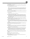
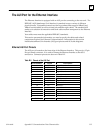
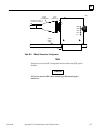
Transceiver Description
Depending on your particular application, any of several types of user-supplied
transceivers may be used. The two most commonly used in industrial environments are:
10Base5 and 10Base2. A typical configuration for each unit is shown in Figures B-3 and
B-4.
TRANSCEIVER CABLE TO
ETHERNET INTERFACE
15-PIN
FEMALE
CONNECTOR
PWR
SQE
XMT
RCV
CP
a44666
15-PIN
MALE
CONNECTOR
10BASE2
COAXIAL
CABLE
BNC
CONNECTOR
BNC
”T”
SQE
must be
ON
.
NOTE
Figure B-4. 10Base2 Transceiver Configuration