


2
2-6 TCP/IP Ethernet Communications User’s Manual – January 1996
GFK-1004B
Press firmly to lock the board in place, but do not force the board.
Note
The Ethernet Controller board will not operate properly if there are
empty slots to the left of the slot you select.
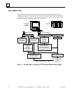
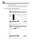
5. Connect the free end of the safety wire (18 inch long green wire attached to the
Ethernet Controller board) to the ground lug at the side of the Series 90-70 PLC rack.
(See Figure 2-2).
Warning
The ground wire must be securely fastened to the chassis of the Series
90-70 PLC rack and the rack must be properly grounded. Failure to do
so may cause personal injury and/or improper operation of the LAN.
6. Connect the transceiver cable into the 15-pin AUI Port of the Ethernet Controller
board. Secure the cable with the slide latch mechanism. The other end of the
transceiver cable should be connected to an external IEEE 802.3 compatible
transceiver which is attached to the Ethernet network. SQE must be enabled on the
transceiver.
7. Set the CPU Run/Stop switch to STOP.
8. Continue with Procedure 2: Verifying Ethernet Interface Power-Up.
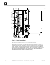
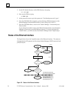
Ethernet Controller Board Installed in Series 90-70 PLC Rack
P
S
U
C
P
a45349
GROUND
WIRE
TRANSCEIVER
CABLE
TO
802.3
TRANSCEIVER
B
T
M
E
T
H
E
R
N
E
T
Figure 2-2. Ethernet Controller Installation in the Series 90-70 PLC
Note
The Ethernet Controller board must be installed in the main rack;
installation in an expansion rack is not supported.