


Contents
xii
TCP/IP Ethernet Communications User’s Manual – January 1996 GFK-1004B
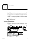
Figure 1-1. Major Components of the TCP/IP LAN 1-1 . . . . . . . . . . . . . . . . . . . . . . . . . . . . . . . . . . . . . . . . . .
Figure 1-2. The Main Tasks for Installing the TCP/IP Ethernet Communications System 1-6 . . . . . . . . . .
Figure 2-1. Ethernet Controller Board 2-2 . . . . . . . . . . . . . . . . . . . . . . . . . . . . . . . . . . . . . . . . . . . . . . . . . . . . .
Figure 2-2. Ethernet Controller Installation in the Series 90-70 PLC 2-6 . . . . . . . . . . . . . . . . . . . . . . . . . . . .
Figure 2-3. States of the Ethernet Interface 2-8 . . . . . . . . . . . . . . . . . . . . . . . . . . . . . . . . . . . . . . . . . . . . . . . . .
Figure 3-1. GEnet System Manager (GSM) on 802.3 LAN 3-1 . . . . . . . . . . . . . . . . . . . . . . . . . . . . . . . . . . . .
Figure 3-2. GSM Main Menu 3-13 . . . . . . . . . . . . . . . . . . . . . . . . . . . . . . . . . . . . . . . . . . . . . . . . . . . . . . . . . . . . .
Figure 3-3. GSM Menu Structure 3-16 . . . . . . . . . . . . . . . . . . . . . . . . . . . . . . . . . . . . . . . . . . . . . . . . . . . . . . . . .
Figure 3-4. Configure a Station Screen 3-18 . . . . . . . . . . . . . . . . . . . . . . . . . . . . . . . . . . . . . . . . . . . . . . . . . . . .
Figure 3-5. Configuration Editor Menu 3-21 . . . . . . . . . . . . . . . . . . . . . . . . . . . . . . . . . . . . . . . . . . . . . . . . . . . .
Figure 3-6. TCP/IP Parameters Screen 3-22 . . . . . . . . . . . . . . . . . . . . . . . . . . . . . . . . . . . . . . . . . . . . . . . . . . . . .
Figure 3-7. Advanced Parameters Menu 3-24 . . . . . . . . . . . . . . . . . . . . . . . . . . . . . . . . . . . . . . . . . . . . . . . . . . .
Figure 3-8. Data Link Parameters Screen 3-25 . . . . . . . . . . . . . . . . . . . . . . . . . . . . . . . . . . . . . . . . . . . . . . . . . .
Figure 3-9. System Parameters Screen 3-27 . . . . . . . . . . . . . . . . . . . . . . . . . . . . . . . . . . . . . . . . . . . . . . . . . . . . .
Figure 3-10. Download Station Screen 3-29 . . . . . . . . . . . . . . . . . . . . . . . . . . . . . . . . . . . . . . . . . . . . . . . . . . . . .
Figure 3-11. Access Station Manager Screen 3-32 . . . . . . . . . . . . . . . . . . . . . . . . . . . . . . . . . . . . . . . . . . . . . . . .
Figure 3-12. List All Stations Screen 3-33 . . . . . . . . . . . . . . . . . . . . . . . . . . . . . . . . . . . . . . . . . . . . . . . . . . . . . . .
Figure 3-13. Setup GSM Menu 3-35 . . . . . . . . . . . . . . . . . . . . . . . . . . . . . . . . . . . . . . . . . . . . . . . . . . . . . . . . . . .
Figure 4-1. Elements of the Communications Request 4-2 . . . . . . . . . . . . . . . . . . . . . . . . . . . . . . . . . . . . . . .
Figure 4-2. Operation of the Communications Request for an Establish Read ChannelCommand 4-5 . .
Figure 4-3. Format of the COMMREQ Status Word (CRS Word) 4-29 . . . . . . . . . . . . . . . . . . . . . . . . . . . . . .
Figure 4-4. Format of the Detailed Channel Status Words (DCS Words) 4-29 . . . . . . . . . . . . . . . . . . . . . . . .
Figure 5-1. Station Manager Accessed Locally through the 9–pin Serial Port by a GSM in
Local Station Manager Mode (or an ASCII Terminal) 5-2 . . . . . . . . . . . . . . . . . . . . . . . . . . . . . .
Figure 5-2. Station Manager Accessed Directly over the Network by a GSM in Network
Station Manager Mode 5-2 . . . . . . . . . . . . . . . . . . . . . . . . . . . . . . . . . . . . . . . . . . . . . . . . . . . . . . .
Figure 5-3. Station Manager Accessed Remotely over the Network by a GSM in Local
Station Manager Mode using the REM (Remote) Command 5-3 . . . . . . . . . . . . . . . . . . . . . . . .
Figure 6-1. Determining the State of the Ethernet Interface 6-4 . . . . . . . . . . . . . . . . . . . . . . . . . . . . . . . . . .
Figure B-1. Serial Cable to Connect GSM (25–Pin Connector) to Ethernet Interface B-2 . . . . . . . . . . . . . .
Figure B-2. Serial Cable to Connect GSM (9–Pin Connector) to Ethernet Interface B-2 . . . . . . . . . . . . . . .
Figure B-3. Transceiver Cable Connection B-4 . . . . . . . . . . . . . . . . . . . . . . . . . . . . . . . . . . . . . . . . . . . . . . . . .
Figure B-4. 10Base2 Transceiver Configuration B-4 . . . . . . . . . . . . . . . . . . . . . . . . . . . . . . . . . . . . . . . . . . . . .
Figure G-1. IP Address Format for Network Classes A, B, C G-1 . . . . . . . . . . . . . . . . . . . . . . . . . . . . . . . . . .
Figure G-2. Connecting Two Networks with a Gateway G-2 . . . . . . . . . . . . . . . . . . . . . . . . . . . . . . . . . . . . .
Figure G-3. Network Configuration Using a Subnet Mask G-3 . . . . . . . . . . . . . . . . . . . . . . . . . . . . . . . . . . .