


B
section level 1
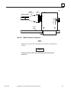
figure_ap level 1
table_ap level 1
B-1
GFK-1004B
Appendix B Communications Ports Characteristics
This appendix describes the Ethernet Interface serial port used to connect to the GSM
and the AUI port used to connect to the network transceiver.
What this Appendix Contains
Information pertaining to the Serial Port for Local GSM communications
Serial Port Pinouts
Serial Cable Diagrams
Information pertaining to the Attachment Unit Interface (AUI) Port for Ethernet
communications
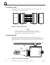
AUI Port Pinouts
AUI Cable Diagram
Transceiver Unit Description
Serial Port for Local GSM Communications
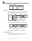
This section presents the information you need to construct a cable for serial
communications between the Ethernet Interface and the Local GSM or other serial
terminal. Information in this section includes serial port settings, pinouts, and cable
diagrams.
Serial Port Settings
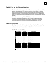
The serial port (COM1) must be set to 9600 bps, 8 bits, no parity, and 1 stop bit.
Serial Port Pinouts
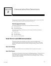
The serial port is located on the front edge of the Ethernet Interface. The serial port is a
9-pin D-type female connector that presents an RS–232 DTE Interface. It is used to
connect the Ethernet Interface to the local GEnet System Manager (GSM). Connector
pinouts are shown in Table B-1.