


1
1-3
GFK-1004B
Chapter 1 Introduction
Maintain Compatibility with other GE Fanuc devices, as well as with devices from
other vendors. The GE Fanuc Series 90–70 PLC with TCP/IP Ethernet Interface is
compatible with the Series 90-30 PLC with TCP/IP Ethernet Interface.
It is also compatible with GE Fanuc Logicmaster 90-70 TCP/IP Ethernet and GE
Fanuc HCT Ethernet products available on DEC, HP, IBM, and other computer
platforms running TCP/IP.
Diagnose and maintain your system, using diagnostic and station management
tools. You can find problems before they become serious. In the event that
communications software upgrades are needed, you can use the network or the
built-in serial port to download the software to the interface.
Indirectly attach to other Local Area Networks and/or wide area networks via third
party IP routers. When configured to use an IP gateway (router), the Ethernet
Interface can communicate with remote PLCs and other nodes reachable through
the router.
Communicate with remote computers via Serial Line Internet Protocol (SLIP)
using modems and/or serial lines. Using third party SLIP software, a remote host
computer can be attached to a TCP/IP network thus allowing it to communicate to
the Series 90 PLC via the Ethernet Interface.
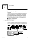
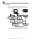
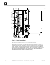
Attachment of the Ethernet Interface to the LAN
The AUI port provides the electrical and mechanical interface to the user-provided
Ethernet transceiver cable, which connects the AUI port to an external user-provided
transceiver. The external transceiver is directly connected to the Ethernet cable.
Various Ethernet baseband media (10Base...) can be interconnected by appropriate re-
peaters. Capabilities and limitations are defined in IEEE 802.3 Chapter 13, “System Con-
siderations for Multi-Segment Networks”.
The Ethernet Controller can operate on any of the following media with the appropriate
user-supplied transceiver cable and transceiver. IEEE 802.3 specifies the definitive re-
quirements of each medium.
10Base5 Coax: 10Base5 uses a 0.4 inch diameter 50–ohm coaxial cable. The maximum
length of a cable segment is 500 meters. The distance between any two stations must be
a multiple of 2.5 meters. A maximum of 100 stations is allowed on a thickwire Ethernet
segment.
10Base2 Coax: 10Base2 uses a 0.2 inch diameter 50–ohm coaxial cable. The maximum
length of a cable segment is 185 meters. A maximum of 30 stations is allowed on a thin-
wire Ethernet segment.
10BaseT: 10BaseT uses a twisted pair cable of up to 100 meters in length between each
node and a hub or repeater. Typical hubs or repeaters support 6 to 12 nodes connected
in a star wiring topology.
10BaseF: 10BaseF has two variations that both use the same type of fiberoptic cable:
10BaseFP can support up to 33 nodes at distances of up to 500 meters from a passive
star; 10BaseFL supports up to 2000 meters between a node and a repeater (a multi-port
repeater would thus constitute a star). Additionally, 10BaseFB provides a means of inter-
connecting (only) repeaters by up to 2000 meters of (the same) fiber optic cable.