


2
section level 1
figure bi level 1
table_big level 1
2-1
GFK-1004B
Chapter 2 Installing the Ethernet Interface
This chapter describes the basic features of the Ethernet Interface, its installation, and a
procedure for its initial checkout on your Ethernet cable. The chapter first provides an
overview of the Ethernet Controller Board, which is the hardware component of the
Ethernet Interface. It is then divided into six sequential Installation Procedures, each
providing an overview of the procedure, explaining the steps to be performed, and de-
scribing the expected results.
As you work through a procedure you may encounter references to the appendices and
other chapters in this manual. These references provide more detailed information
about the subject under discussion.
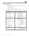
The installation procedures described in this chapter are listed below:
Procedure 1: Installing the TCP/IP Ethernet Controller Board in the PLC Rack -
Required
Procedure 2: Verifying Proper Power-Up of the Ethernet Interface - Required
Procedure 3: Configuring the Ethernet Interface with the Logicmaster 90-70
Configurator - Required
Procedure 4: Configuring and Downloading a Station - Required
Procedure 5: Testing the Ethernet Interfaces on the Network - Optional
Procedure 6: Pinging the Ethernet Interfaces on the Network - Optional
Some of the procedures require prior cable plant design and installation.
After completing the Installation Procedures you will gain an understanding of the parts
of the network and how they fit together. You will also have confidence that your equip-
ment is working properly.
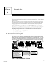
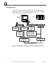
Ethernet Interface Hardware Overview
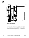
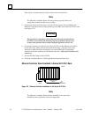
The Ethernet Controller board is mounted in the Series 90-70 PLC rack. It is connected to
an external transceiver via a user-provided transceiver cable. The external transceiver is
then connected to the Ethernet cable. The figure below shows the layout of the Ethernet
Controller board.